Comments (60)
 zalo
commented on June 21, 2024
2
zalo
commented on June 21, 2024
2
It might be nice to do Linear Sweeps too. I wrote a small sweeping implementation using CoACD to see how bad it would be:

# Linear Sweep
import coacd
a_mesh = a.to_mesh()
parts = coacd.run_coacd(coacd.Mesh(a_mesh.vert_properties[:, :3], a_mesh.tri_verts)) # a list of convex hulls.
print("COACD found", len(parts), "parts")
sweep = manifold3d.Manifold()
for i, part in enumerate(parts):
    manifold_part = manifold3d.Manifold.from_mesh(manifold3d.Mesh(part[0], part[1]))
    swept_convex_part = manifold3d.Manifold.batch_hull(
        [manifold_part,
         manifold_part.translate(0.4, 0.4, 0.4)])
    sweep += swept_convex_part
return sweep
Problem here is:
[2023-11-22 10:44:45.680] [CoACD] [info] Compute Time: 4.466729499981739s
[2023-11-22 10:44:45.681] [CoACD] [info] # Convex Hulls: 72
Linear Sweep took 4584.762300015427 ms
CoACD takes 97.5% of the time 😅
Sweeping each triangle individually:
a_mesh = a.to_mesh()
swept = manifold3d.Manifold()
for tri in a_mesh.tri_verts:
    hull = manifold3d.Manifold.hull_points(
        [a_mesh.vert_properties[tri[0], :3],
         a_mesh.vert_properties[tri[1], :3],
         a_mesh.vert_properties[tri[2], :3],
         a_mesh.vert_properties[tri[0], :3] + 0.4,
         a_mesh.vert_properties[tri[1], :3] + 0.4,
         a_mesh.vert_properties[tri[2], :3] + 0.4])
    swept += hull
return swept
Results in a better mesh, and completes in only 382.6230999547988 ms
Manifold is too much faster than the supporting libraries 😂
from manifold.
 elalish
commented on June 21, 2024
2
elalish
commented on June 21, 2024
2
Thanks for the analysis; I definitely don't want to take a dependency on CGAL. And honestly, neither convex decomposition nor Minkowski sums are high on my priority list. We have much more important things to tackle, like overlap removal, smoothing, and remeshing. I also have an idea for making @zalo's offsetting algorithm a lot more efficient, which I think could be quite useful.
from manifold.
 pca006132
commented on June 21, 2024
2
pca006132
commented on June 21, 2024
2
I see lines using a HalfEdge.face index right into the vertPos array
Can you point out which line it is? I don't think it is correct.
Each face i has 3 halfedges with indices of 3*i, 3*i+1, 3*i+2, which you can iterate over using the NextHalfedge function. pairedHalfedge is just the index of the paired halfedge of the current edge. startVert and endVert are the vertex indices in vertPos.
from manifold.
 ng-dmc
commented on June 21, 2024
2
ng-dmc
commented on June 21, 2024
2
Hi, what do you guys think about approach in https://github.com/iGame-Lab/PFPOffset, is it worth consideration?
from manifold.
pca006132
commented on June 21, 2024
1
For negative offset, just subtract the object from the bounding box, do a positive offset, and subtract again?
from manifold.
pca006132
commented on June 21, 2024
1
Was thinking about if it is practical to integrate CGAL into manifoldcad for the purpose of convex decomposition and minkowski. I did some benchmark with CGAL's convex decomposition, thought the result may be useful so I will share it here.
It seems that apart from convex decomposition, Nef Polyhedron construction is also really slow, perhaps due to the exact arithmetic required. On my computer, it takes 0.26s to construct a sphere with 8192 triangles. For context, manifold can construct and do 3 set of boolean operations between spheres with 32768 triangles using a single core, and 12 sets if we enable multiple cores. And the time for constructing CGAL's Nef polyhedron increases slightly faster than linear: the running time increases 5 times when the number of faces increases by a factor of 4.
For the actual decomposition operation, I think it is far from optimal. For example, the convex decomposition of union of two spheres (8192 triangles) gives 572 parts in 14s. Note that the boolean operation is using the exact arithmetic kernel, so this cannot be due to floating point inaccuracy. And this part number increases when the number of faces increase.
nTri = 512
to Polyhedron took 8.5056e-05 sec
conversion to Nef Polyhedron took 0.0138034 sec
boolean took 0.110264 sec
decomposed into 168 parts
decomposition took 1.19174 sec

nTri = 2048
to Polyhedron took 0.000207077 sec
conversion to Nef Polyhedron took 0.0449367 sec
boolean took 0.397265 sec
decomposed into 310 parts
decomposition took 3.87086 sec

nTri = 8192
to Polyhedron took 0.000774715 sec
conversion to Nef Polyhedron took 0.227489 sec
boolean took 1.42059 sec
decomposed into 572 parts
decomposition took 14.1461 sec
In case someone is interested in the code:
#include <CGAL/Exact_predicates_exact_constructions_kernel.h>
#include <CGAL/Nef_polyhedron_3.h>
#include <CGAL/Polyhedron_3.h>
#include <CGAL/convex_decomposition_3.h>

#include <chrono>
#include <iostream>

#include "manifold.h"

using namespace manifold;

using Kernel = CGAL::Epeck;
using Polyhedron = CGAL::Polyhedron_3<Kernel>;
using HalfedgeDS = Polyhedron::HalfedgeDS;
using NefPolyhedron = CGAL::Nef_polyhedron_3<Kernel>;

template <class HDS>
class BuildFromManifold : public CGAL::Modifier_base<HDS> {
 public:
  using Vertex = typename HDS::Vertex;
  using Point = typename Vertex::Point;
  BuildFromManifold(const Manifold manifold) : manifold(manifold) {}
  void operator()(HDS &hds) {
    // Postcondition: hds is a valid polyhedral surface.
    CGAL::Polyhedron_incremental_builder_3<HDS> B(hds, true);
    auto mesh = manifold.GetMeshGL();
    B.begin_surface(mesh.NumVert(), mesh.NumTri(), mesh.NumTri() * 3);

    for (size_t i = 0; i < mesh.vertProperties.size(); i += mesh.numProp) {
      B.add_vertex(Point(mesh.vertProperties[i], mesh.vertProperties[i + 1],
                         mesh.vertProperties[i + 2]));
    }
    for (size_t i = 0; i < mesh.triVerts.size(); i += 3) {
      B.begin_facet();
      for (const int j : {0, 1, 2}) B.add_vertex_to_facet(mesh.triVerts[i + j]);
      B.end_facet();
    }
    B.end_surface();
  }

 private:
  const Manifold manifold;
};

int main(int argc, char **argv) {
  for (int i = 0; i < 8; ++i) {
    Manifold sphere = Manifold::Sphere(1, (8 << i) * 4);
    BuildFromManifold<HalfedgeDS> build(sphere);
    std::cout << "nTri = " << sphere.NumTri() << std::endl;

    auto start = std::chrono::high_resolution_clock::now();
    Polyhedron poly;
    poly.delegate(build);
    auto end = std::chrono::high_resolution_clock::now();
    std::chrono::duration<double> elapsed = end - start;
    std::cout << "to Polyhedron took " << elapsed.count() << " sec"
              << std::endl;

    start = std::chrono::high_resolution_clock::now();
    NefPolyhedron np(poly);
    end = std::chrono::high_resolution_clock::now();
    elapsed = end - start;
    std::cout << "conversion to Nef Polyhedron took " << elapsed.count()
              << " sec" << std::endl;

    start = std::chrono::high_resolution_clock::now();
    NefPolyhedron np2(np);
    np2.transform(
        CGAL::Aff_transformationC3<Kernel>(CGAL::Translation(), {0.5, 0, 0}));
    np = np.join(np2);
    end = std::chrono::high_resolution_clock::now();
    elapsed = end - start;
    std::cout << "boolean took " << elapsed.count() << " sec" << std::endl;

    start = std::chrono::high_resolution_clock::now();
    CGAL::convex_decomposition_3(np);
    std::cout << "decomposed into " << np.number_of_volumes() << " parts"
              << std::endl;
    end = std::chrono::high_resolution_clock::now();
    elapsed = end - start;
    std::cout << "decomposition took " << elapsed.count() << " sec" << std::endl
              << std::endl;
  }
  return 0;
}
from manifold.
zalo
commented on June 21, 2024
1
I think I've made a theoretical breakthrough... when the voronoi regions are set to the circumcircles of each triangle with a reflex edge, then the voronoi diagram perfectly cuts along each triangle edge in one pass (with a ~-0.00011% total volume deviation in 250ms for 224 parts).
There's a funny thing though... for obtuse triangles, the circumcenter is outside the triangle, which you might think causes issues... but Voro++ resolves it correctly by putting the voronoi region correctly outside the cell's coordinate.

The second thing I had to solve for is there are a bunch of situations where the circumcircles of two triangles perfectly overlap... I think I have a solution where I joggle the vertices of just those triangles going in, and then unjoggle them coming out (which should restore the original shape, and is a built-in option in qhull that I had to reimplement).
I think I'm converging on an exact algorithm that has a constant hull output of 2*(reflex edges) (which is better than CGAL's worst case of (reflex edges)^2), which means it'll be ready for codification into C++ soon... where we'll be able to test how useful it is for the operations that need it 💪


Also, if I can use Voro++'s "Custom Walls" feature with manifolds for a restricted tesellation, then that should save on needing to intersect with the original part, which will probably also vastly improve performance... maybe 10x!
from manifold.
pca006132
commented on June 21, 2024
1
Yes. Alternatively you can also do impl.halfedge_[i].pairedHalfedge/3
from manifold.
 pentacular
commented on June 21, 2024
pentacular
commented on June 21, 2024
You run the risk of self-intersection.
Also, offsetting by the tangent of the vertex won't offset the adjacent face by a fixed amount, which may give uneven tolerance across the face.
from manifold.
pca006132
commented on June 21, 2024
So maybe we can compute the offset of each selected faces and add them to the vertices? Not sure about self intersection though.
from manifold.
elalish
commented on June 21, 2024
Yeah, I was thinking about adding the vertex normal as a const input to the Warp function to allow this kind of thing, but indeed, it is very easy for a warping function to introduce self-intersections. The "right" way to offset a mesh is to do a Minkowski operation with a sphere (OpenSCAD supports this) but it's very slow and dramatically explodes the number of faces.
from manifold.
 thehans
commented on June 21, 2024
thehans
commented on June 21, 2024
To avoid self intersections, you need to guarantee that the input is convex. So what is needed is a convex decomposition operation (then offset each convex piece, then union to get the final result).
I wonder if I can just offset each vertices according to their tangent? Although we may need to recompute the tangent if we only selected a subset of faces connecting to that vertex. OK this will not work.
I don't think a vertex has any specific "tangent", maybe you mean the vertex normal?
Vertex normal makes a bit more sense as that is a concept from the field of graphics. But i'd consider it more like a hack/fudged values that looks ok to the eye, than something of rigorously defined geometry.
Imagine translating each face by the offset, along its normal; then conceptually extend each face until it once again intersects at new edges/vertices. That's where you want the vertex to end up, but I'm not entirely sure if the straight average of face normals, applied to the vertex results in this transformation or if there is more to it.
from manifold.
elalish
commented on June 21, 2024
The reason a Minkowski sum is the "right" way is that for a general vertex (not symmetric, more than three faces), when you offset the faces, they will no longer meet up at that same single vertex (in any position). The simplest alternative is just to offset the triangles exactly along their face normals, then stitch the edge and vertex gaps with new faces, but again it only works on convex polyhedra and it explodes the number of faces rapidly.
An alternative approach to adjusting tolerance is to design things parametrically in the first place, so they can simply be rapidly regenerated to adjusted dimensions. This is the approach I always took with OpenSCAD, and it'll work equally well with Manifold.
I tried for some time (years ago) to create a 3D straight skeleton algorithm, which would solve mesh offsetting, but it turned out to be more difficult than I imagined. I'm not tempted to spend much time on it anymore, but I agree it would be a nice algorithm to have.
from manifold.
zalo
commented on June 21, 2024
The dumbest possible Minkowski algorithm I know (for a convex “tool” object) is to go through each face of one mesh, hull the other mesh to each of the vertices of each face, and then union them all together with the original mesh.
The hulls are all parallelizable, there are a ton of duplicate vertices, and it’s one giant union… I wonder how fast it would be?
EDIT: Seems like there might be some simple exact convex decomposition algorithms out there too, though the hulling step here might be slow…
https://www.reddit.com/r/GraphicsProgramming/s/0jGSbAPnxF
from manifold.
pca006132
commented on June 21, 2024
The hulls are all parallelizable, there are a ton of duplicate vertices, and it’s one giant union… I wonder how fast it would be?
I think it will not scale well for meshes with over a thousand faces...
Seems like there might be some simple exact convex decomposition algorithms out there too, though the hulling step here might be slow…
We want to avoid exact convex decomposition not because the algorithm itself is hard, but because exact convex decomposition will create many parts for very simple geometries, e.g. cube - sphere. In that case it is not better than the "dumbest possible" solution you said.
I actually implemented something that can deal with concave geometries, see #415 (comment)

The reason I was holding it back is because
- The algorithm itself will create self-intersections when the curvature is too large / offset is too large that requires changing the topology globally. So I need another algorithm to compute some kind of decomposition that can avoid the self-intersection, and I found a flaw in the other algorithm I wrote (not hard to fix, just need to rewrite some code).
- It is doing some approximation for concave surfaces. It makes me feel a bit uncomfortable...
- We should round over those convex edges and vertices, similar to minkowski with a sphere with high
$fn. But this is tricky and the paper I read just hand waived over this. I experimentally figured out a solution that seems to work. While the idea is simple, it is not very easy to implement, especially when I have some "clever" (complicated) index manipulation within the code... - It is unclear to me how I should clean this up and submit in a PR. Seems too experimental comparing with other parts of the library.
In short: I procrastinated about this. I prefer doing dumb optimizations that doesn't exercise my brain that much :P
from manifold.
thehans
commented on June 21, 2024
We want to avoid exact convex decomposition not because the algorithm itself is hard, but because exact convex decomposition will create many parts for very simple geometries, e.g. cube - sphere.
What? cube and sphere are already convex. The convex decomposition of a convex geometry is just the one geometry
edit: ah, sorry i misinterpreted the dash as a random separator, not an difference operation.
from manifold.
pca006132
commented on June 21, 2024
I mean cube - sphere, e.g.

from manifold.
pca006132
commented on June 21, 2024
The algorithm I was implementing is from the paper "Offset Triangular Mesh Using the Multiple Normal Vectors of a Vertex" and "A 3D surface offset method for STL-format models". Instead of vertex normals, they use normals from incident faces/edges. Each convex edge contribute two normals, one from each incident face. For concave edges, the algorithm computes an "average" vector. Below is a diagram for the 2D case:

This is the case when there is only 1 concave edge. Note that the "normal" in this case is no longer a unit vector. When there are two consecutive concave edges, where consecutive means consider all the incident edges in cw/ccw order, there is a 3D case. However, when you get to three or more consecutive concave edges, this method doesn't really work, the paper just say something like compute the solution for every 3 consecutive normals and then average them...
After this we still have another problem: How should we compute the "blend surface" by subdivision? Again, for the convex case it is simple, just add the two vectors and normalize them. However, when we have concave edges, this does not work because the "average normal" is not a unit vector, normalizing the sum will lose the length value. Take the average of the length of the two vectors is not a solution either. I experimentally find out (read: guess and try to compute it) that if the "average normal" is the "average" of 1 or 2 normals, say
It would be great if someone can give me some help on the math things. I don't know much about the math here.
from manifold.
zalo
commented on June 21, 2024
I think there's a simpler (if slower) solution to offsetting that preserves manifoldness and adds fillets...
def offset(a, distance, resolution=20):
    a_mesh = a.to_mesh()
    sphere = manifold3d.Manifold.sphere(abs(distance), resolution)
    # Hull B for each triangle of A
    a_combo = a # Should be a copy
    for tri in a_mesh.tri_verts:
        hull = manifold3d.Manifold.batch_hull(
            [sphere.translate(a_mesh.vert_properties[tri[0], :3]),
             sphere.translate(a_mesh.vert_properties[tri[1], :3]),
             sphere.translate(a_mesh.vert_properties[tri[2], :3])])

        # Union or Difference depending on the Offset Amount
        if distance > 0:
            a_combo += hull
        else:
            a_combo -= hull
    return a_combo
Original Shape:

Offset Positive took 1418.94 ms:

Offset negative took 1488.11 ms:

Minkowski Sums are a generalization of this:
def minkowski(a, b):
    a_hull    = a.hull(); b_hull = b.hull()
    a_convex  = a.get_volume() == a_hull.get_volume()
    b_convex  = b.get_volume() == b_hull.get_volume()
    a_mesh = a.to_mesh()

    # Easy Case: Just hull b for each vertex of a
    if a_convex and b_convex:
        return manifold3d.Manifold.batch_hull(
            [b.translate(v) for v in a_mesh.vert_properties[:, :3]])

    # Harder Case: Hull B for each triangle of A
    # Do some kind of convex decomposition here?
    if (not a_convex) and b_convex:
        a_union = a
        for tri in a_mesh.tri_verts:
            hull = manifold3d.Manifold.batch_hull(
                [b.translate(a_mesh.vert_properties[tri[0], :3]),
                 b.translate(a_mesh.vert_properties[tri[1], :3]),
                 b.translate(a_mesh.vert_properties[tri[2], :3])])
            a_union += hull
        return a_union

    # Else, we need to do a more complicated Minkowski sum with Convex Decomposition
    # Or a really really slow TriangleXTriangle Super Sum...
    assert False, "Non-Convex on Non-Convex minkowski Not Implemented Yet! Fall back to CGAL or something..."
Instead of doing it per-triangle, you’d want to do it per convex sub-component, which is where a fast exact convex decomposition would come in handy…
from manifold.
elalish
commented on June 21, 2024
I have to admit, that brute force approach to offsetting has some nice robustness properties. I'm surprised it's that fast - obviously not great at scale, but I think most people using an offset probably want to apply it to fairly simple objects anyway. I don't think we need to do a general Minkowski op - we got started here because we noticed that the only thing anyone ever used a Minkowski for was a sphere anyway, so better to stick with offsetting for simplicity. It also gives @pca006132's CSG tree optimizations a chance to shine, with all those repeated ops.
from manifold.
zalo
commented on June 21, 2024
After this we still have another problem: How should we compute the "blend surface" by subdivision? Again, for the convex case it is simple, just add the two vectors and normalize them. However, when we have concave edges, this does not work because the "average normal" is not a unit vector, normalizing the sum will lose the length value. Take the average of the length of the two vectors is not a solution either. I experimentally find out (read: guess and try to compute it) that if the "average normal" is the "average" of 1 or 2 normals, say n1=avg(u,v),n2=avg(u′,v′) (where avg is the mysterious average operator, whatever that means), we can do n3=avg(normalize(u,u′),normalize(v,v′)) and n3 is the vertex in the blended surface. I checked this to work with some pyramid with star-shaped base. But this doesn't work for 3 or more normals!
It would be great if someone can give me some help on the math things. I don't know much about the math here.
CAD Kernels (like OpenCASCADE) mesh all surfaces by subdivision of some 2D function parameterized by u,v.
For a 3-way fillet blend, I think CAD kernels try to use circular/spherical blends when possible, but will also use a polynomial to construct an interpolating surface when circular blends are not possible… I’d have to check how OpenCascade does it…
My naive recommendation would be to use barycentric interpolation of the triangle positions/normals to perform the interpolation… but I’m on the go right now, so I can’t review my usual sources 😅
If you want to see how a CAD Kernel handles it really quick, you can use my little CAD playground webapp to create a box, subtract a box from that, and select the inner three corners with the fillet tool…
https://leapmotion.github.io/LeapShape/
(hopefully it all still works…)
from manifold.
zalo
commented on June 21, 2024
One quality boost that just occurred to me is to rotate the hull spheres so that one of their vertices align to the mesh’s surface normal.
This should be a free change that addresses the flat inner face seen here without increasing the resolution:

Perhaps it can be an optional arg on the offset() function 😄
I would still like to figure out a reasonable full minkowski sum implementation though…
from manifold.
elalish
commented on June 21, 2024
Interesting idea. Out of curiosity, what makes you attracted to the full minkowski sum op? I was always surprised it was included in OpenSCAD at all, since in all my time using that program I could never find a useful mental model for that op, so I pretty much never used it.
from manifold.
zalo
commented on June 21, 2024
I’ll admit, the only non-convex/non-convex sum I’ve ever wanted to do is a toroid sweep along a spline path (and there are far more efficient ways of doing that).
My primary fascination with Minkowski sums has been in collision detection, where two arbitrary objects collide when the “Minkowski Difference” intersects the origin:
The bottleneck for making physics engines that don’t rely on convex primitives has always been the difficulty in computing the Minkowski sums in a reasonably fast manner (which, of course, we’ll never do exactly on meshes quickly). I find the visualization mostly educational 😄
Maybe it’s fine to have a brute force implementation for it, since few will ever use it outside of as a curiosity…
Either way, I think the convex/convex case, and the non-convex/convex case have enough fun uses that optimized implementations would make a worthwhile addition to the toolkit.
The unionRound implementation is a fun example of that:
https://github.com/TLC123/OpenSCAD_stuff
(This function in particular would benefit the most from @pca006132 ’s fast mesh offsetting method, since the slowest part is constructing a bunch of Minkowski() sphere-dilated offset meshes 😄)
from manifold.
pca006132
commented on June 21, 2024
Interesting. I actually asked my friends doing research in robotics about usage of minkowski sum, they said that it can be used in collision detection but it is so slow that nobody really uses it.
Regarding CoCAD: It does approximate convex decomposition. I think it is faster than exact convex decomposition and give you a lot less parts. However, those approximate convex parts are not suitable for doing minkowski sum, you will get self-intersections. And it is surprising to know that the decomposition step is slower than doing hundreds of unions. I guess our optimizations are worth it.
Btw thanks for the pointer for computing blends, will look into it. I am lacking a lot of the basic knowledge about graphics and CAD.
from manifold.
pca006132
commented on June 21, 2024
I tested the per triangle minkowski sum with openscad, it is much slower than convex decomposition when the operand is large, e.g. spheres with $fn=100, which a lot of users do use.
from manifold.
zalo
commented on June 21, 2024
I think approximate methods are slower because they are iterative, and aiming for the smallest number of hulls possible.
I’m hopeful there are fast and exact methods (like this guys’s greedy one: https://www.reddit.com/r/GraphicsProgramming/s/0jGSbAPnxF ) that still produce vastly fewer convex parts than the number of triangles on the mesh 😄
I’d probably try to implement it by modifying the existing hull algorithm…
Could you share the OpenSCAD code you tested and the relative timings?
from manifold.
zalo
commented on June 21, 2024
I have a new dumb algorithm in mind for convex decomposition:
- Find the most concave edge in the manifold
- Split the manifold by a plane along this edge.
- Decompose the resulting manifolds and repeat until there are no more concave edges.
It could be interesting to select the plane’s splitting angle, there are a few options:
- Pick the bisecting plane
- Pick a plane parallel to one of the adjoining triangles
- Pick a plane parallel to both adjoining triangles
- Pick a plane snapped to the nearest cardinal direction (may simplify the resulting chunks?)
My cheater heuristic will probably be:
- If the concave angle is 90°, then cut parallel to each of the adjoining triangles
- Else, cut along the bisector.
Will need to test this on a bunch of meshes (both organic and inorganic), but I think this might give the best cuts on the most meshes.
And, depending on how fast “split by plane” is, this could all run at usable speeds 😄
The CGAL Pages describing their algorithms have been wonderful for clarifying my thinking:
https://doc.cgal.org/latest/Convex_decomposition_3/index.html
https://doc.cgal.org/latest/Minkowski_sum_3/index.html
Looking forward to trying this out once I’m back from holiday 😄
from manifold.
pca006132
commented on June 21, 2024
I feel like picking a plane snapped to the nearest cardinal direction is probably the fastest way of split by plane, considering how the collider works.
I was thinking about something similar for the algorithm I was working on, but instead of finding concave edges I try to find pairs of faces that the swept volume will intersect (which I call conflicting faces). With those pairs, just do the decomposition by the bisecting plane. For efficiency, try to randomize a bit and try several possible cuts for each level (a bit like Monte Carlo tree search but not as sophisticated), as one cut may eliminate multiple pairs of conflicting faces. It will also prioritize cuts that have roughly equal number of pairs of conflicting faces on both parts, as we can do the decomposition of two parts in parallel.
This can work for the algorithm I was working on because it does not require the parts to be convex, this is just to avoid having conflicting faces.
And yeah the CGAL algorithm description is amazing.
from manifold.
elalish
commented on June 21, 2024
Interesting. These ideas remind me a bit of binary space partitioning trees (BSP), which are sometimes used for mesh booleans. Sounds like they might be better for this.
from manifold.
zalo
commented on June 21, 2024
Bisecting plane sounds good, but how do you calculate it for the swept surface?
Interesting. These ideas remind me a bit of binary space partitioning trees (BSP), which are sometimes used for mesh booleans. Sounds like they might be better for this.

(Author of RealTimeCSG and Chisel, the best brush package for Unity)
I think the tricky part is that going to brushes from meshes needs a convex decomposition 😄
I’m tempted to add a “method” arg to the function for the different speed and exactness tradeoffs… it would be cool to be able to trade exactness for not having your computer crash trying to do the operation…
I think a good additional heuristic for splitting planes is trying to get it to contain multiple concave edges at once, which should vastly cut down on the number of convex parts for “blocky” objects (though it’ll do little for “organic” objects).
from manifold.
pca006132
commented on June 21, 2024
No, I am I only calculate it for two planes, because I only need to separate them so their swept volumes will not be intersecting.
For the heuristic, I think apart from whatever geometry things that you come up with, adding Monte Carlo tree search (e.g. try not only the edge with the highest weight, but several ones and use the best one) will probably help a bit.
from manifold.
zalo
commented on June 21, 2024
Hrmmm, testing out my Solid Exact Convex Decomposition, it seems like it takes about as long as CoACD and VHACD, but outputs 2-6x more convex parts (close to the order of as many concave edges as there are on the model)...


So far, not seeing the benefit except for very blocky models, which it decomposes great.
Perhaps it's time to explore the surface decomposition methods...
https://dpd.cs.princeton.edu/Papers/ChazelleDobkinShourabouraTal.pdf
(Which I'm skeptical of, since the pieces could generate hulls that extend outside the bounds of the original part...)
Or the CGAL Method:
https://alexandria.tue.nl/openaccess/Metis212139.pdf
Or perhaps another one...
from manifold.
pca006132
commented on June 21, 2024
The issue with the number of convex parts is the reason we think that mesh offsetting using minkowski sum and convex decomposition will not scale.
Doesn't seem solvable without doing some approximation, but existing approximate convex decompositions are not suitable for minkowski sum.
For the openscad test, I will post it later this week. I am currently in hospital and does not have access to my computer for several days. I was just modifying the minkowski sum code for manifold backend in openscad, and run them against some benchmarks (in the manifold integration PR for openscad).
from manifold.
pca006132
commented on June 21, 2024
Btw, wondering if porting CGAL's convex decomposition function will make it significantly faster. For openscad, iirc the bottleneck is currently in the convex decomposition part.
CGAL is only accepts Nef polyhedron for the convex decomposition, which uses exact arithmetic and operations on them are known to be pretty slow.
They don't have any parallelization for the decomposition, hopefully we can find some opportunities for that.
from manifold.
elalish
commented on June 21, 2024
Regarding @zalo's simple offset method - does negative offsetting work when you use convex decomposition? That feels like a pretty useful feature, but I'm not sure that Minkowski can do that. I would prefer a spherical offset that goes negative and positive, to a Minkowski that takes different convex objects but only goes one way.
from manifold.
elalish
commented on June 21, 2024
A different way we could optimize @zalo's method is instead of doing 3D convex decomposition, check each vertex for convexity. Any vertex that is entirely reflex will not contribute a fillet, so the sphere can be left off of the hulls for all triangles using that vertex. Would only help on that class of vertices, but these are also the verts that will give convex decomposition it's biggest difficulties.
from manifold.
elalish
commented on June 21, 2024
We could also optimize @zalo's method by hulling triangles, edges, and vertices separately. Convex edges become cylinders, non-reflex vertices are spheres, and triangles are extruded. This should cut down the number of faces going through boolean ops by a factor of 6 or more. Plus we actually wouldn't need to use convex hulls at all.
from manifold.
zalo
commented on June 21, 2024
A different way we could optimize @zalo's method is instead of doing 3D convex decomposition... Any vertex that is entirely reflex will not contribute a fillet, so the sphere can be left off of the hulls for all triangles using that vertex.
I'm not sure I fully understand this one... I don't think the red circled vertices can be ignored?

We could also optimize @zalo's method by hulling triangles, edges, and vertices separately. Convex edges become cylinders, non-reflex vertices are spheres, and triangles are extruded. This should cut down the number of faces going through boolean ops by a factor of 6 or more. Plus we actually wouldn't need to use convex hulls at all.
I'm not sure if triangles can be treated as direct extrusions along the normal with finite-resolution spheres... likewise I'm not sure if the cylinders' edge vertices would line up... would need a lot of stitching...
This sort of thinking is getting closer to the convolution method, which is outlined for spheres in the papers @pca006132 linked earlier:
https://www.cad-journal.net/files/vol_1/CAD_1(1-4)_2004_285-291.pdf
qu2003.pdf
And which is generalized to all meshes here:
https://web.archive.org/web/20220527183520/http://masc.cs.gmu.edu/wiki/SimpleMsum
My mind has still been thinking about whether non-planar cuts can be used in constrained divisions... sort of like voronoi diagrams...
I feel like I could artfully place non-planar cuts and divisions within meshes to get much fewer convex parts than my naive algorithm so far... but I haven't quite figured out how to formalize it yet...
Maybe:
- K-Means Cluster the Reflex Edges
- Place a half-space through every reflex edge towards the cluster center
- Intersect each cluster's half-spaces to get non-planar cutting volumes...
That could be a really interesting idea...
Also, CGAL's implementation of convex decomposition looks like it'd be a little painful to reimplement...
from manifold.
pca006132
commented on June 21, 2024
Also, CGAL's implementation of convex decomposition looks like it'd be a little painful to reimplement...
true... maybe we should try something simpler.
Btw the work you mentioned is interesting, wondering if it is as efficient as they claimed why is it not used in other packages? They seem to provide the source code for the algorithm.
from manifold.
zalo
commented on June 21, 2024
The code request email form is down, and he works at iRobot instead of the university (which owns the code?) now…
Also, I suspect it’s not that much simpler than the CGAL solution…
I’m currently churning on the viability of non-planar cuts… but it might make sense to have the slow “per-triangle” implementation for now… linear sweeps can be sped up 2x by only sweeping triangles facing in the direction of the sweep, so that might be a good method too…
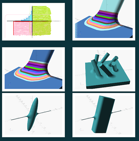
from manifold.
zalo
commented on June 21, 2024
I finally had a chance to implement an early version of my non-planar cutting implementation...
It relies on voronoi diagrams: it puts two points into the diagram on either side of each reflex edge to create a voronoi cell that splits the edge. The resulting voronoi regions do a pretty good job splitting across each reflex edge, for an almost exact decomposition with 2x the number of primitives as reflex edges, and very quickly (relative to my prior method and other approximate decomposition methods...)
My hope, at some point, is to find a weighted voronoi diagram generation library to encode the triangle edge lengths into the diagram, which should hopefully let it do an exact decomposition in one pass. And maybe merge non-splitting voronoi regions to vastly reduce the number of hulls...
Even still, the results are pretty fun (Black Points represent the Voronoi Cell Points):
Just Voronoi Splitting (408 parts in 514ms):

Voronoi Splitting + Plane Splitting Refinement for Exactness (737 parts in 1118ms):

Just Voronoi Splitting (120 parts in 222ms):


I think a lot of the striped pieces might be able to be merged without compromising the exactness (too much?)
Just Voronoi Splitting (12 parts in 12ms):


Anyway, here's the code:
https://gist.github.com/zalo/4c13d9eebd029d5b8ba42e5f29c663b4
The two major improvements would be:
- Finding a weighted 3D power diagram implementation and testing whether this allows for exact decomposition in one pass
- Determining how to merge non-splitting adjacent voronoi cells (to vastly reduce the number of output hulls).
scipy's qhull wrapper was the only voronoi diagram implementation that I could find for Python, do you guys know of any good free ones with good licenses?
(also, the reason why I'm pursuing it again this week is to use Manifold with Physics Engines like PhysX, which can only collide convex shapes 🙃 )
from manifold.
zalo
commented on June 21, 2024
Ahh, for the infamous "sphere-in-cube" model, I can get that down to 224 parts in 400ms if I keep track of which points were spawned by which faces, and hull the regions belonging to the same triangle together after the fact.

For a comparison of default settings (where VoACD (or "Voronoi"ACD) is mine):
| Algorithm | # Hulls | Execution Time | Volume Change |
|---|---|---|---|
| VHACD (Default Settings) | 64 parts | 4034ms | 12.34% Volume ⬆️ |
| CoACD (Default Settings) | 72 parts | 4423ms | 6.65% Volume ⬆️ |
| VoACD with merging same faces | 224 parts | 400ms | 1.52% Volume ⬆️ |
| VoACD++* with merging same faces | 224 parts | 300ms | 1.02% Volume ⬆️ |
| VoACD without merging same faces | 408 parts | 568ms | 0.714% Volume ⬆️ |
| VoACD++* without merging same faces | 408 parts | 443ms | 0.148% Volume ⬆️ |
| VoACD with Plane Splitting | 659 parts | 1122ms | 0.00173% Volume ⬇️ |
| VoACD++* with Plane Splitting | 458 parts | 635ms | 0.00019% Volume ⬇️ |
Which I'm pretty happy with; at the cost of being 3.5x more expensive to simulate at runtime, it's 10x faster to bake and 8x more accurate than VHACD. One downside is that it has no obvious tunable parameters to trade speed for part count 🤔
Also, all of the steps are currently being done in sequence in Python, so it should speed up significantly with multithreading in C++... So now there are two guaranteed areas for improvement (threading and weighted voronoi/power diagram) and one possible area for improvement (merging hulls)...
The goal for all of this would be to use it with Manifold and physx-js-webidl (or somesuch) for a virtual woodworking simulator... maybe in VR?
EDIT*: Found a Weighted-Voronoi Diagram/Power Diagram/Laguerre Tesellation library: Voro++ (and its Python lib, tess), replacing qhull wrapped by scipy... Numbers in the table updated under VoACD++; volume difference got dramatically better, as predicted! (But I didn't expect execution time to also get better 😅 )
Now the fastest config is 13x faster to bake and 12x more accurate than VHACD. 😄 (While still costing 3.5x as much at runtime 🙃 )
from manifold.
elalish
commented on June 21, 2024
Pretty cool. For your talk of colliders, are you actually wanting something so precise? I would be tempted to make something like a BVH tree and hull the leaves at some level, maybe iterate to refine a little. No reason the parts need to be disjoint, right? Just a thought.
from manifold.
zalo
commented on June 21, 2024
Pretty cool. For your talk of colliders, are you actually wanting something so precise? I would be tempted to make something like a BVH tree and hull the leaves at some level, maybe iterate to refine a little. No reason the parts need to be disjoint, right? Just a thought.
That’s not a bad idea; how would you suggest the BVH partition the mesh?
I already tried K-Means on the Vertices yesterday, and it didn’t yield particularly efficient results, but perhaps targeting the reflex edges in a more approximate way might still be alright… maybe via support vector machine…
After playing with it all day yesterday, I’m pretty convinced of the utility of Voronoi Diagrams, and a function that takes in a manifold and a set of (weighted) points, and splits the manifold into sub-manifolds. This is the essence of “Voronoi Fracture” algorithms, which can replicate additionally interesting effects like crystal lattices, wood grain, bricks, etc. as well as being the foundation of my convex decomposition and probably a bunch of other interesting decompositions.
In fact, the three most useful low-level library utils for all the effects in this thread are:
- Parallel Batch Many Hulls
- Voronoi Fracture (based on Voro++ or Geogram’s Isolated Delaunay Module
- Convex Decomposition (that can switch between VHACD (header only lib), CoACD, and/or mine (all MIT Licensed) via enum)
from manifold.
elalish
commented on June 21, 2024
I don't know - it was just an idle thought. I agree though, Voronoi partitions are quite useful. In 2D, the dual of a voronoi partition is a Delaunay triangulation, right? I wonder what the 3D equivalent is?
from manifold.
zalo
commented on June 21, 2024
The 3D Equivalent is the Delaunay Tetrahedralization, which is enormously useful for Finite Element Simulation. (See WebGL FEM Simulation I made a while ago: https://zalo.github.io/TetSim/ ; consider “Digital Molecular Matter”)
I think the broken out Geogram library is probably a better/cleaner bet for getting both 3D Voronoi and 3D Delaunay (though it might need the full Geogram for constraining the tetrahedralization to the bounds of the manifold), but there are also specialized libraries for this, like fTetWild:
https://github.com/wildmeshing/fTetWild
Worthy of note is the fact that tetrahedra are also convex… but they’re far too numerous to do minkowski sums or rigidbody physics with; I’d go straight for FEM simulation if fTetWild was built into Manifold.
The benefit of FEM is that you get deformations straight-forwardly… so any woodworking or cooking simulation would get to benefit from deformations and soft body physics implicitly 😄
from manifold.
zalo
commented on June 21, 2024
I'm beginning the C++ Integration... so far, I have Voro++ and a Voronoi Fracture Function (with Python Binding) integrated:
master...zalo:manifold:feat-voacd
The actual VoACD Implementation is going to take a little more diagnostic troubleshooting to match the Python Implementation... specifically, I think, the subroutine that finds all triangles with at least one reflex edge, and the circumcircle routine...
This is probably just my noobishness with Halfedges showing, but could someone clarify how the HalfEdge indices, HalfEdge.face indices, and vertPos indices are related? Periodically, I see lines using a HalfEdge.face index right into the vertPos array... which implies that edges, vertices, and faces are all interchangeable somehow😕?
from manifold.
elalish
commented on June 21, 2024
Yeah, the only funny thing is that i/3 == halfedge_[i].face, and the code uses both approaches pretty often.
from manifold.
zalo
commented on June 21, 2024
And this is probably obvious, but does impl.halfedge_[impl.halfedge_[i].pairedHalfedge].face give the adjacent face connected to impl.halfedge_[i].face?
from manifold.
pca006132
commented on June 21, 2024
@zalo thinking about it, I think the algorithm CGAL uses is worse-case optimal, as there is a construction that requires O(r^2) convex pieces where r is the number of reflex edges? https://www.cs.princeton.edu/~chazelle/pubs/ConvexPartitionPolyhedra.pdf
from manifold.
zalo
commented on June 21, 2024
Where does it say that? I can’t think of a construction that requires r^2; mine pretty much only does r*2, iirc…
(also, fwiw, I’m keeping my implementation warm as the default branch here https://github.com/zalo/manifold ; I tried to break it out from Manifold, but it relies too much on internal data structures to be separated cleanly.)
from manifold.
pca006132
commented on June 21, 2024
@zalo The lower bound is here:

Did not read into their construction to see if it really holds though.
from manifold.
pca006132
commented on June 21, 2024
*see figure 4.
from manifold.
zalo
commented on June 21, 2024

This is only r^2 if you only make planar slices from the vertical axis.
You can get it down to 8 convex parts if you first slice it horizontally in between the top and bottom, and then proceed with their vertical plane slice algorithm.
My algorithm theoretically gets you 12 convex parts, since creates voronoi chunks on each face adjacent to a reflex edge.

I'll admit though, some of the chunks coming out of my algorithm appear to be too-large, causing them to overlap with other reflex edges (outputting not-exactly convex parts), and the theoretical bound on convex parts is sort of worthless unless we can think of a straight-forward algorithm to achieve it in the general case. 😅
from manifold.
pca006132
commented on June 21, 2024
@zalo I was trying to use your branch in openscad, but it says there are many degenerate triangles or degenerate voronoi cells, it is normal?
e.g.
[ERROR] Degenerate Voronoi Cell at Index: 213
[ERROR] Degenerate Voronoi Cell at Index: 233
[ERROR] Degenerate Voronoi Cell at Index: 174
[ERROR] Degenerate Voronoi Cell at Index: 219
[ERROR] Degenerate Voronoi Cell at Index: 231
[ERROR] Degenerate Voronoi Cell at Index: 277
[ERROR] Degenerate Voronoi Cell at Index: 164
[ERROR] Degenerate Voronoi Cell at Index: 168
[ERROR] Degenerate Voronoi Cell at Index: 238
[ERROR] Degenerate Voronoi Cell at Index: 344
[ERROR] Degenerate Voronoi Cell at Index: 86
[ERROR] Degenerate Voronoi Cell at Index: 88
[ERROR] Degenerate Voronoi Cell at Index: 90
[ERROR] Degenerate Voronoi Cell at Index: 92
[ERROR] Degenerate Voronoi Cell at Index: 94
[ERROR] Degenerate Voronoi Cell at Index: 154
[ERROR] Degenerate Voronoi Cell at Index: 161
[ERROR] Degenerate Voronoi Cell at Index: 163
[ERROR] Degenerate Voronoi Cell at Index: 166
[ERROR] Degenerate Voronoi Cell at Index: 210
[ERROR] Degenerate Voronoi Cell at Index: 211
[ERROR] Degenerate Voronoi Cell at Index: 212
[ERROR] Degenerate Voronoi Cell at Index: 214
[ERROR] Degenerate Voronoi Cell at Index: 215
[ERROR] Degenerate Voronoi Cell at Index: 216
[ERROR] Degenerate Voronoi Cell at Index: 218
[ERROR] Degenerate Voronoi Cell at Index: 220
[ERROR] Degenerate Voronoi Cell at Index: 295
Circumradius: -14.8087
Circumradius: -14.8087
Circumradius: -14.8087
Circumradius: -25.8262
Circumradius: -14.8087
Circumradius: -25.8262
Circumradius: -14.8087
Circumradius: -25.8262
Circumradius: -14.8087
Circumradius: -25.8262
Circumradius: -25.8262
Circumradius: -25.8262
Circumradius: -25.8262
Circumradius: -25.8262
Circumradius: -14.8087
Circumradius: -14.8087
Circumradius: -14.8087
Circumradius: -14.8087
Circumradius: -14.8087
Circumradius: -25.8262
Circumradius: -14.8087
Circumradius: -25.8262
Circumradius: -14.8087
Circumradius: -25.8262
Circumradius: -14.8087
Circumradius: -25.8262
Circumradius: -25.8262
Circumradius: -25.8262
Circumradius: -25.8262
I admit though, the triangles are pretty bad... maybe we need to do remeshing or mesh refinement?

from manifold.
zalo
commented on June 21, 2024
Yeah, that’s pretty normal (though it doesn’t always cause problems), but you probably do need to do some form of mesh refinement…
The issue with the circumcircle formulation is that long-skinny triangles tend to have massive circumcircles that are well-outside of their bounds… I suspect my voronoi formulation is only “guaranteed”(?) to work if the surface triangulation is Delaunay… or if all the circumcenters lie within the borders of the triangles 🤔
(Sometimes it works anyway, but not guaranteed 🫠)
Perhaps the formulation is still too immature to use without mesh refinement 🙃
Perhaps better to stick to CGAL 😓
from manifold.
pca006132
commented on June 21, 2024
Interesting, maybe can combine with mesh refinement later. I am just curious about how this performs comparing with the one in CGAL. (when I was waiting for a meeting, picked up the old code and run them again)
but at least there is no longer the old segfault!
from manifold.
pca006132
commented on June 21, 2024
Looks interesting, it seems that it does not rely on sampling, and seems that it can scale to pretty large meshes. Probably need to play with their demo and see.
from manifold.
elalish
commented on June 21, 2024
Certainly interesting - I'm curious what kinds of results it gets with a uniform offset - they seem to show a lot of examples of offsets that vary from one side of the object to the other, which makes it harder to evaluate the results. It also appears that repo has a dependency on CGAL, which we would not want to take. Can you look at see how feasible it would be to remove that dependency or replace it with functions we have in Manifold (Manifold is in some sense a CGAL competitor)?
from manifold.
Related Issues (20)
- triangulator optimization HOT 10
- Python API: batch_hull fails bizarrely HOT 9
- CMake silently downloads Thrust HOT 3
- API Documentation link in README does not exist HOT 2
- GetMesh core dump with SparseIndices too large HOT 16
- better error handling
- Properly handle negative volume meshes HOT 3
- how to properly use runOrigialID
- Better documentation for FillRule HOT 18
- Using Manifold-3d npm package from node? HOT 3
- wasm build problem 'Failed to resolve import "./built/manifold"' HOT 7
- mesh size approximation HOT 21
- Wrong pkg-config package name for Clipper2 dependency HOT 2
- Python created object reports as non-manifold. HOT 3
- Watertightness of Mesh with an Edge Shared by 4 Faces
- vertex halfedge iterator
- Manifold 2.4.5 release tar.gz is incomplete HOT 3
- Vec out of Range HOT 8
- Python binding needs two import call HOT 4
- Manifold Decompose doesn't preserve vertex properties HOT 4
Recommend Projects
-
 React
React
A declarative, efficient, and flexible JavaScript library for building user interfaces.
-
Vue.js
🖖 Vue.js is a progressive, incrementally-adoptable JavaScript framework for building UI on the web.
-
 Typescript
TypeScript is a superset of JavaScript that compiles to clean JavaScript output.
-
TensorFlow
An Open Source Machine Learning Framework for Everyone
-
Django
The Web framework for perfectionists with deadlines.
-
 Laravel
A PHP framework for web artisans
-
D3
Bring data to life with SVG, Canvas and HTML. 📊📈🎉
-
Recommend Topics
-
javascript
JavaScript (JS) is a lightweight interpreted programming language with first-class functions.
-
web
Some thing interesting about web. New door for the world.
-
server
A server is a program made to process requests and deliver data to clients.
-
Machine learning
Machine learning is a way of modeling and interpreting data that allows a piece of software to respond intelligently.
-
Visualization
Some thing interesting about visualization, use data art
-
Game
Some thing interesting about game, make everyone happy.
Recommend Org
-
Facebook
We are working to build community through open source technology. NB: members must have two-factor auth.
-
Microsoft
Open source projects and samples from Microsoft.
-
Google
Google ❤️ Open Source for everyone.
-
Alibaba
Alibaba Open Source for everyone
-
D3
Data-Driven Documents codes.
-
Tencent
China tencent open source team.
from manifold.