Implementation of a laserscanner on a FPGA. In a high-speed polygon scanner system, the laser is deflected by a rotating prism or reflective mirror.
The position of the laser is determined via a sensor such as a photodiode.
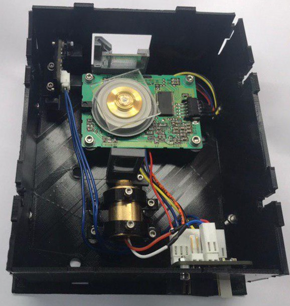
Code is tested on the system shown in the image above, branded as Hexastorm.
The bill of materials (BOM) and links to FreeCad and PCB designs can be found on Hackaday.
The code took most inspiration from LDGraphy.
On Raspberry, install libatlas so latest Numpy, etc. can be installed via pip.
sudo apt update
sudo apt install libatlas3-base
Install required libraries
pip3 install -r requirements.txtMake folder and install litex, this downloads and installs a lot!
mkdir ~/litex
cd ~/litex
wget https://raw.githubusercontent.com/enjoy-digital/litex/master/litex_setup.py
chmod +x litex_setup.py
./litex_setup.py init install --user
Install Hexastorm in develop mode so you can edit.
python3 setup.py develop --userInstall ice40 and yosys
apio install yosys
apio install ice40
Install icezprog
git clone https://github.com/cliffordwolf/icotools
cd ~/icotools/examples/icezero
make icezprog
mv icezprog ~/.local/binThe following parameters describe the system.
| parameter | description |
|---|---|
| RPM | revolutions per minute of the rotor |
| Start% | fraction of period where scanline starts |
| End% | fraction of period where scanline stops |
| SPINUP_TIME | seconds system waits for the rotor to stabilize speed |
| STABLE_TIME | seconds system tries to determine position laser with photodiode |
| FACETS | number of polygon facets |
| DIRECTION | exposure direction, i.e. forward or backward |
| SINGLE_LINE | system exposes fixed pattern, i.e. line |
| SINGLE_FACET | only one of the facets is used |
Using the above, the code determines the number of bits in a scanline. Via a serial port interface the user can push data to the scanner. A line is preceded with a command which can be SCAN or STOP. The data is stored on the chip in block ram. Once turned on, the scanner reads out this memory via First In First Out (FIFO).
| command | reply |
|---|---|
| STATUS | retrieve the error state and state of the laser scanner. This is the default reply of each command. |
| START | enable the scanhead |
| STOP | stop the scanhead |
| MOTORTEST | enable the motor |
| LASERTEST | turn on the laser |
| LINETEST | turn on the laser and the motor |
| PHOTODIODETEST | turn on motor, laser and turn off if photodiode is triggered |
| WRITE_L | next byte will be stored in memory |
Look at the test folders and individually tests on how to use the code. The whole scanhead can be simulated virtually. As such, a scanner is not needed.
Only one of the 32 block rams is used.
The laser can be pulsed at 50 MHZ but data can only be streamed to the laser scanner at 25 megabits per second.
Parameters can not be changed on the fly. The binary has to be recompiled and uploaded to the scanhead. This is typically fast, i.e. seconds.
The current implentation is targeted at a system with one laser bundle
System is for writing to, i.e. exposing, a substrate. Reading should also be possible to enable optical coherence tomagraphy.
System has no link for LIDAR measurements, circuit can be found here.
The FPGA controls all the stepper motors. At the moment it is not possible to use GCODE or apply acceleration profiles.
Most of these implementation can be removed by improving the code. The current focus is on a proof of principle. Next step would be to create a copy of beagleg with a FPGA code parser. In a later stage, they might be merged.
An instruction video is shown below;

Examples used to gain experience with migen.
For image operations, opencv is required.
pip3 install opencv-pythonAlso install the following dependencies
sudo apt install -y libopenjp2-7 libilmbase-dev libopenexr-dev libgstreamer1.0-dev ffmpegTwo camera's have been tried; uEye camera and Arducam Global shutter ov2311. Currently, the ov2311 chip is used.
Disadvantages; the uEye is more expensive, drivers require an account and there is no good Python driver.
Advantages; the product is more mature.
On Ueye website select Ueye 2240 monochrome. Download and install the driver for
linux, arm v7, as this is the raspberry pi platform. A python library for the camera is available in the source code.
My version can be installed via uEyeCamera.
Install my version of the Python libary ArducamPython.
In the current board, the SPI1-1 select pin is not routed to the correct pin on the Raspberry. In /boot/config.txt ensure you have the following
dtoverlay=spi0-1cs
dtoverlay=spi1-1cs,cs0_pin=7
There should not be dtparam=spi=on, somewhere. This would enable two chip selects for SPI0 and create a conflict with the pin select of SPI1. You can check the configuration via
ls /dev/spi*
sudo vcdbg log msgIn the current scanhead, I2C is used to set the power of the laser via a digipot. I2C can be enabled on the Raspberry Pi as follows.
i2cdetect -y 1This will produce output, here 28 is the address of the I2C device.
     0  1  2  3  4  5  6  7  8  9  a  b  c  d  e  f
00:          -- -- -- -- -- -- -- -- -- -- -- -- --
10: -- -- -- -- -- -- -- -- -- -- -- -- -- -- -- --
20: -- -- -- -- -- -- -- -- 28 -- -- -- -- -- -- --
30: -- -- -- -- -- -- -- -- -- -- -- -- -- -- -- --
40: -- -- -- -- -- -- -- -- -- -- -- -- -- -- -- --
50: -- -- -- -- -- -- -- -- -- -- -- -- -- -- -- --
60: -- -- -- -- -- -- -- -- -- -- -- -- -- -- -- --
70: -- -- -- -- -- -- -- --An alternative to apio is yowasp or compile from source. Apio is chosen as compilation takes a long time on a Raspberry. Yowasp comes with python support but only works on a X86 system. Yowasp takes a lot of time to run the first time. The FPGA toolchain can be build from source via ICE40.


