GithubHelp home page GithubHelp logo

rtd266xflash's Introduction

RTD266xFlash

This is a combination of an Arduino sketch, a Python script and a C# GUI application to read and write the firmware of the Realtek RTD266x flat panel display controller. The Arduino code is based on ladyada's project.

There are special features included for a 3.5" HDMI display manufactured by KeDei, which is equipped with an RTD2660: you can replace the boot logo with a custom logo, change the background and foreground colors and modify the "HDMI" pop-up. The custom logo needs to be 204x72 pixels and may only contain black and white pixels.

Custom logo

Usage

In order to modify the RTD266x's firmware, you need to establish a connection to the chip. There are two ways to do that:

  1. You can connect the display via HDMI to a Raspberry Pi, enable the I²C HDMI driver and read/write the firmware using the Python script without any additional hardware. The firmware will be stored in a file which you can open and modify with the C# GUI tool. The modified file is then written back to the display with the Python script.

  2. You connect an Arduino to the display's I²C pins using a modified HDMI cable. The Arduino is connected to a PC/laptop and controlled with the C# GUI tool.

If you don't have Microsoft Visual Studio to compile the C# GUI tool, you can download the EXE file from the releases.

Method 1: Arduino

Compile the RTD266xArduino sketch with the Arduino IDE and download it onto your Arduino. You can close the Arduino IDE afterwards.

Connecting

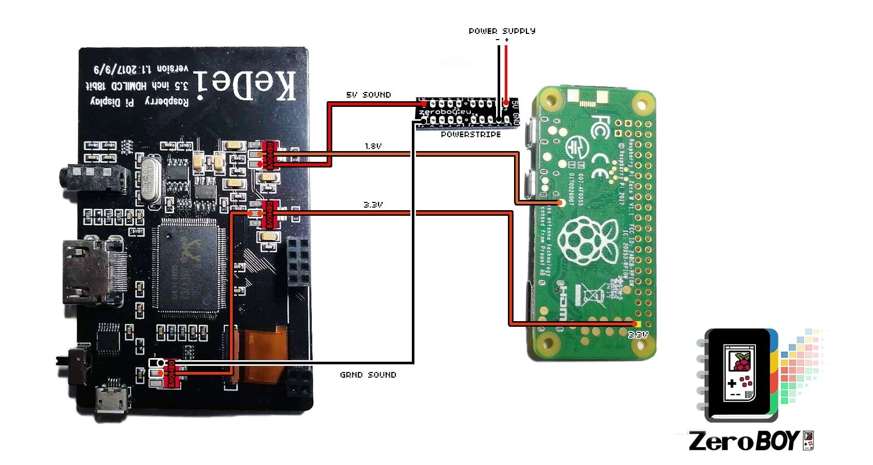
The communication between display and Arduino is done via I²C which is accessible on the VGA and HDMI ports of RTD266x. Connect SCL, SDA and GND with the corresponding Arduino pins.

For an Arduino Uno and an HDMI connector type A, this would be:

Pin name Arduino Uno HDMI type A
SCL A5 15
SDA A4 16
GND GND 17

There are no additional pull-ups required, they are already on the RTD266x PCB.

Connect the display and Arduino as mentioned above. Power on the display first, then the Arduino.

A flashing user LED on the Arduino indicates a problem with the connection. Reset the Arduino to try again and use the GUI tool to read the error info.

Setup example

GUI tool

Start RTD266xFlash.exe and select Connect directly with an Arduino. Select the COM port your Arduino is connected to and click Connect. If there was an error it will tell you what went wrong. You can click Read status to check the connection and read some info about the flash chip. It should return values different from 0x00 and 0xFF. If it doesn't, try again or reset the Arduino.

If you get an error about an unknown JEDEC id, uncomment or add the correct JEDEC id in rtd266x.cpp. Compile and download the sketch again to your Arduino and try again.

Screenshot of GUI tool

Ruby tool

Instead of the GUI tool written in C#, you can use a Ruby tool on the command line written by kivikakk.

To read the flash into the file flash-contents.bin, call it like this:

ruby flash.rb SERIAL dump

Replace SERIAL with your serial port (for example COM1 on Windows, /dev/ttyACM0 on Linux or /dev/cu.usbmodem3201 on a Mac).

To write back the firmware, use this command:

ruby flash.rb SERIAL write FILE [OFFSET LENGTH]

Call the tool without parameters to get a detailled description of its parameters.

Method 2: Firmware images with Python script

For this method you need a Raspberry Pi running a current version of Raspbian or any derivative. Use a standard HDMI cable to connect the display to the Raspberry Pi. In your /boot/config.txt file you need to add the following line to enable the I²C on HDMI interface:

dtparam=i2c2_iknowwhatimdoing

For the Raspberry Pi 4 and modern firmware you need to change the line

dtoverlay=vc4-fkms-v3d

to

dtoverlay=vc4-kms-v3d

You will also need to install the I²C Python library with this command:

sudo apt-get install python-smbus

After a reboot, enable the I²C driver by executing:

sudo raspi-config

Navigate to Interfacing Options, I2C and select Yes. Use Back and Finish to leave the configuration tool.

Get a list of available I²C busses:

i2cdetect -l

You can then scan for I²C devices with this command on a specific bus:

sudo i2cdetect -y I2CBUS

where I2CBUS is the bus number you got from the previous command, i.e. sudo i2cdetect -y 2.

It should find a device at address 4a.

To download the Python scripts, run the following commands:

  1. cd ~
  2. git clone https://github.com/floppes/RTD266xFlash.git
  3. cd RTD266xFlash/RTD266xPy

You are now ready to read the display's firmware with this command:

python rtd266x_flash.py -i I2CBUS -r 524288 -f out.bin

Replace I2CBUS with your bus number. The number after parameter -r is the firmware's size in bytes (512 x 1024 = 512 KB). This will take about 2 minutes. Transfer the file out.bin to your PC/laptop where you have the GUI tool RTD266xFlash.exe. Start it and select Firmware images. Select out.bin as the input file and configure the modifications you want to perform. Click Modify firmware and save the modified firmware file.

Screenshot of GUI tool

Screenshot of GUI tool

Transfer the modified firmware file to the Raspberry Pi and run

python rtd266x_flash.py -i I2CBUS -d out.bin -f out_modified.bin

where I2CBUS is the bus number and out_modified.bin is the modified firmware file. This will write all modified sectors of file out_modified.bin to the display, skipping the unmodified sectors to speed things up. Enjoy your modified firmware!

Expert knowledge: details of firmware modifications

Attention: Before you modify your firmware, create a backup of the original firmware!

An Intel 8051 MCU is integrated in the RTD266x which runs the firmware. If you compile the source code (Source 1 and source 2) and set the compiler to output the assembler listings, you can easily find matching code areas within the binary firmware. By manipulating the instructions, we can modify the firmware's behaviour.

Here are some examples for the KeDei 3.5" display. There are different firmware versions for different PCB revisions and panel types. All firmwares are 512 KB. They are assigned numbers to refer to them:

# Hardware MD5 Hash SHA1 Hash
1 PCB V 1.0 C501EB83693372E1089B096B024F2E9F 08B253C9B757BC700AFC057F3836878BE866C05C
2 PCB V 1.1, panel type 1 (SKY035S13B00-14439) 83B41D1682E7CB7DED3A0241518A3D96 1C675660BF478E687CD09912EF77D2A86E93525E
3 PCB V 1.1, panel type 2 (SKY035S13D-199) v1 0FA74E1AF51B56A84AA4D4DD4D97383E 09E16041E390F9804EA6F734DCB1AACC4A0DC97B
4 PCB V 1.1, panel type 2 (SKY035S13D-199) v2 22AF4BE65892FA772D8699DD030837DC 3E80A0B3C1DA0E726A1FCF6D31DED497C0B65429
5 PCB V 1.1, panel type 3 (SKY035S13E-180) v1 906A447A4E0D182669228EC75E581E78 9DAC069E130FC7638D90E031C2E36819344703AD
6 PCB V 1.1, panel type 3 (SKY035S13E-180) v2 B55F67DA7A609C954EBB75FCDF877F7D DEC9911C8C1D150D069BAB1D1E42792665E62AD8

Change background color to black

The background color is set by calling function CAdjustBackgroundColor. For firmware #1 this function is located at 0xD237 - 0xD27A, for firmware #2 at 0xD432 - 0xD475, for firmware #3 at 0xD2A5 - 0xD2E8 and at 0xD2C9 - 0xD30C for firmware #5. At function offsets 0x2C (#1: 0xD263, #2: 0xD45E, #3: 0xD2D1, #5: 0xD2F5) and 0x3C (#1: 0xD273, #2: 0xD46E, #3: 0xD2E1, #5: 0xD305) the instruction is 0xE0 (MOVX A,@DPTR). By changing this to 0xE4 (CLR A) the background color is always set to 0x000000, which corresponds to black.

Change logo colors

The boot logo uses two colors, which are picked from a color palette consisting of 16 3-byte (red, green, blue) entries. The palette is located at 0x13A31 (firmware #1, #2, #3 and #5). The foreground color is 0xFFFFFF (white) at 0x13A3A. The background color is 0x0000FF (blue) at 0x13A5B. By changing 0x13A5D to 0x00 we can change the background to black.

Change "HDMI" pop-up text

After the display is powered on and has shown it's logo, a small pop-up shows the input source. The text "HDMI" can be changed easily. You won't find the ASCII characters in the firmware, but you can refer to tGlobalCharWidth in OSD/OSD003/OsdRes003.c to decode and encode a string. Some wide characters like A, G, M, W etc. are composed of two font entries. You can find the "HDMI" string by searching for 19 14 1E 1F 1A 00 (offset 0x12346 for firmware #1, #2, #3 and #5). It can be replaced by a custom string but shouldn't be much longer.

Disable "HDMI" pop-up

The "HDMI" pop-up is shown by the function CShowNote. It is located at 0x14733 (firmware #1, #2, #3 and #5). By changing it's first instruction at 0x14733 to 0x22 (RET), we force an immediate return from this function and no pop-up is shown.

rtd266xflash's People

Contributors

floppes avatar kivikakk avatar tampertronics avatar

Stargazers

 avatar  avatar  avatar  avatar  avatar  avatar  avatar  avatar  avatar  avatar  avatar  avatar  avatar  avatar  avatar  avatar  avatar  avatar  avatar  avatar  avatar  avatar  avatar  avatar  avatar  avatar  avatar  avatar  avatar  avatar  avatar  avatar  avatar  avatar  avatar  avatar  avatar  avatar  avatar  avatar  avatar  avatar  avatar  avatar  avatar  avatar  avatar  avatar  avatar  avatar  avatar  avatar  avatar  avatar  avatar  avatar  avatar  avatar  avatar  avatar  avatar  avatar  avatar  avatar  avatar

Watchers

 avatar  avatar  avatar  avatar  avatar

rtd266xflash's Issues

JEDEC ID: 0x856013 Cannot setup chip commands. The flash chip id is unknown.

Hello, first of all, thanks for the awesome job, the following is not quite an issue but much more an information request.

I'm trying to get my 7 inches Kedei flashed (using the RPi method), this screen is also managed by a RTD2660 chip.
When I launch the python script it stops with the following error message :

JEDEC ID: 0x856013
Cannot setup chip commands. The flash chip id is unknown.

The script might not be ready for this device but I'm wondering if by any way I could make it work with my device?

Below are some pictures of the board in the case it brings more information to your knowledge :

20201201_111050
20201201_111118
20201201_111258

Unknown firmware on latest KeDei KD0350AV02 3.5" TFT

Thanks for this utility, I have successfully used it to flash one of these in the past but the latest one I bought results in "Error: Unknown Firmware". The PCB looks the same as the previous version but when I run diff on the out.bin I had dumped from the old screen compared to this it reports it is different. I will attach the dump file and picture from my latest screen.

out.bin.2021-11-22.zip
image

Support for MPI7002 7"

Hi!
Please add support for new display

If it possible please make patch for this:
there is backlight adjust button, if short click the button, the brightness is added (+10).
if you hold it for more than 3 seconds, the screen turns off. to turn on the screen, press the button again.
BUT there is an error. If I want to turn off the screen, then the brightness is added first, then the screen turns off.
and it may happen that the next switching on of the screen will be with a brightness equal to 10

another way (for patch) switch on always with 100 bright

out.bin.zip

New JEDEC id 0x856014 won't flash

This is related to #4 as it appears this chip (P25Q80H) is more or less identical to that one, just bigger.

I'm using Python to work with HDMI to dump the firmware from my chip, but it's not working so well. I can get it to read off the chip, but the data is volatile when I do - that is, I can read twice and get two slightly different files. I also am completely unable to write at all:

Resetting device...
Entering ISP mode...
Reading chip data...
JEDEC ID: 0x856014
ID: 0x8513
Status: 0xfc
Clearing lock bits...
Status: 0xfc
Writing data from file some_file.bin to offset 0...
Erasing sector at address 0x0
Writing 256 bytes to address 0x0
CRC validation failed! Expected 0x5, received 0xba
Error: cannot program flash!
Resetting device...

Is there an easy way to fix this? I checked some of the relevant code and if I didn't misread, the 0x85 at the front of the flash code should be enough on its own to apply the necessary fixes.

rtd2660 800x480 unknown firmware

hello, first of all, thank you for the effort and your amazing work
I can modify a kedei 3.5 rpi screen perfectly

but when I try to modify a cheap Aliexpress rtd2660h board controller I can write full firmwares but I can't change the boot logo or the input pop up
direct arduino says: error! cannot identify chip

and with the "firmware image option" says: unknown firmware
here is my actual firmware
firmware-ykr.BIN.zip

thank you for your time

EEPROM ZB25VQ40ATIG

Hi Floppes,
i do not know ho to contact you.
I have a PCB800099 V9 board with RTD2660 and ZB25VQ40ATIG EEPROM
https://datasheet.lcsc.com/lcsc/2003172038_Zbit-Semi-ZB25VQ40ATIG_C495748.pdf

I try to backup the firmware before loading other ones.
I successfully connect to the BOARD through ARDUINO UNO with your sketch and with "RTD266xFlash.exe" :

Connecting...
Connection error: timeout, retrying... (1/5)
Connection error: checksum error, retrying... (2/5)
Connection successful!
Reading status info... done
Manufacturer ID: 0x5E (Unknown)
Device ID: 0x12 (Unknown)
JEDEC Manufacturer ID: 0x5E (Unknown)
JEDEC Memory Type: 0x60
JEDEC Capacity: 0x13 (Unknown)
Status: 0x181C

But I am blocked in the "Read EEPROM" section. Indeed, I do not know what are the parameter of memory to be sure to read all the eeprom through "start adress" and "lenth" values.
Can you help?
Thank a lot.
Brice

Update readme because issues

I am working with PCB800099 on RTD 2660 chip and found some undocumented problems.

  1. Change BAUD_RATE to 9600 in RTD266xArduino and in RTD266xFlash.exe, otherwise Connection Timeout error
  2. Uncomment string:
    {"W25X40" , 0xEF3013, 512, 256, 64},
    in rtd266x.cpp in Arduino IDE window, otherwise Unknown JEDEC error

PS. It is useful to debug connection issues using famous "i2c_detect" Arduino sketch. Should spit out something like:

I2C device found at address 0x37  !
I2C device found at address 0x4A  !
I2C device found at address 0x4B  !
I2C device found at address 0x50  !

Question: 7" capability ?

Hi, I've read that's for KeDei 3.5" but I've boght 7" HDMI waveshare display which seems to use the same RTD2660H IC. So I'm wondering if there something I should look after before testing? Or it's explicitly for 3.5" displays?

self.i2c = SMBus(interface) IOError: [Errno 2] No such file or directory

Hello,

sorry to disturb you but i try your tutorial with a RPI4 and i have this error :
python rtd266x_flash.py -r 524288 out.bin Traceback (most recent call last): File "rtd266x_flash.py", line 41, in <module> rtd = RTD266x(args.interface, 0x4A) File "/home/pi/RTD266xFlash/RTD266xPy/rtd266x/rtd266x.py", line 24, in __init__ self.i2c = SMBus(interface) IOError: [Errno 2] No such file or directory

the first issue is i cant detect anything with sudo i2cdetect -y 2 only sudo i2cdetect -r -y 11 and then i found the 4A I2s module.

so i found with googling : in /boot/config.txt look for the [pi4] section and set this value dtoverlay=vc4-kms-v3d,
delete the "f" of fkms, and then i was able to sudo i2cdetect -r -y 11 and found the 4A I2s of the screen but the above error is when i try to read the flash memory with python rtd266x_flash.py -r 524288 out.bin.

i understand that i should modify the bus number, because you use the 2 in your Pi3 config, but its slightly different with a Pi4, which is the bus 11 or i2s-11...if i have well understanding...

Any idea please?

Thanks!

////////////////////////////////////////////////////////////////////////////////////////////////////////////////////////////////////////////////////////////

EDIT : GET IT WORKING ON RPI4 :
for those who use a Rpi4, the way is different than on Pi3 : check at : "https://www.ddcutil.com/raspberry/"
so i have just modify the boot.txt with dtoverlay=vc4-kms-v3d and installed ddcutil and comment the dtparam=i2c2_iknowwhatimdoingnot needed for Pi4,

the read firmware command is :
python rtd266x_flash.py -i 11 -r 524288 out.bin where 11 is the bus interface...that why the error is complaining about "interface" value that was not provided in the command line...lol...i have understand what i am doing...

and flash command is :
python rtd266x_flash.py -i 11 -d out.bin out_modified.bin

it works! no more blue background awfull screen and no more pop up messages lol, thanks!

composite input option in kedei 3.5"

Thank you for everything you do and for the ease of being able to write and modify our RTD2660.

I've been exploring the various modifications that people can achieve for a short time, and a question arose that could be an addition to your software.

We know that the RTD266x has AV/VGA/HDMI inputs, but on each board, only some are enabled or only one input is enabled, as is the case with my screen, which is the same as the one in the picture in your readme, a Kedei 3.5" HDMI. My question is:

Could the function be added to your software or in some way independently enabled, for example, the composite AV input, understanding that we would have to solder an additional cable to use the input and assign a simple pull-down as a source change button in the case of having two video sources active? Or even better for some projects, in your program, being able to select between a single input, for example, HDMI/AV, so that a source button is not needed.

I hope I'm not being a bother with my question, but this would help several projects that only have composite video signal.

And again, THANK YOU

Cannot connect to gui tool

I'm facing the same issue a few folks had. Uploaded arduino i2c scan and it's finding a lot of devices:

Scanning...
I2C device found at address 0x37 !
I2C device found at address 0x3A !
I2C device found at address 0x4A !
I2C device found at address 0x4B !
I2C device found at address 0x50 !

In the gui it's retrying 5 times and cannot connect. Tried 115200 also 9600 same effect. Any help? After many months ago I successfully connected them but not now.. I'm using arduino pro micro

RTD2556 + EEprom 25Q80DV

Hi,
I've a display board with ICs I wrote in the title.
I edited the arduino sketch to recognize the Jedec ID of this eeprom (0xEF4014) and then tried your C# application and works!
Only problem is that chip is 1MB and the application stops at 512k, so there is no way to read the entire eeprom... So I'm asking if you can update the application for reading/writing 1MB (8Mbit) chips.
I've set the correct value in the arduino sketch but looks like is not this the problem (I wrote the same values of the already present W25X80 changing only the name)

python script doesn't work

In the file rtd266x.py, there is in line 2 :
from rtd266x.smbus import SMBus

But there is no file smbus.py in the directory rtd266x

Help with flashing

Hi!

Not really an issue...

I've flashed a wrong firmware on my device, on windows using the RTDTool...
Device is rtd2550 and the flashed firmware is for rtd2556.

But I've made an backup of the original firmware before flashing!

Now the device won't power up anymore.

Then I found about this project. Set up an rpi3 and used the py script to dump the firmware. Compared it to the file I used to flash and it's not the same.
Then I when I try to flash my backup it gives me crc error and aborts.

My controller board is bricked? :-(

PCB80052 firmware unknown

Hi, firstly thank you so much for your dedication and hard work.

I successfully read the firmware from the above board (which has an RTD2660H) using your python tool.

When I try to open it in the editor I get "unknown firmware"

Is there any way I can work with it. I tried opening it in a hex editor but I'm not really sure what I'm looking for, I did find a sequence of bytes that seem similar when looking to disable the call to the hdmi source dialogue.
PCB80052.zip

Any help would really be appreciated, thank you in advance.

Firmware dump for Elecrow RC050 5" display

Good evening! I'm attaching the firmware dump I pulled from this device: https://www.elecrow.com/wiki/index.php?title=RC050_5_inch_HDMI_800_x_480_Capacitive_Touch_LCD_Display_for_Raspberry_Pi/_PC/_SONY_PS4

It's a 800 x 480 display with capacitive touchscreen. Fairly popular for SBC projects.
out.zip

I tried to use the GUI to change the logo image. The tool warned me that it is an unknown firmware, but the autodetect appeared to be successful and it generated an out_modified.bin. However, using the python script to try to flash it back to the display, I got this error:

Resetting device...
Entering ISP mode...
Reading chip data...
JEDEC ID: 0x856013
ID: 0x8512
Status: 0x9c
Clearing lock bits...
Status: 0x9c
Writing sectors from file out_modified.bin which differ from sectors of file out.bin...
155648
Erasing sector at address 0x26000
Writing 256 bytes to address 0x26000
Writing 256 bytes to address 0x26100
CRC validation failed! Expected 0xb7, received 0xad
Resetting device...

Any ideas what I might try?

Support for Waveshare 4.3"

Hello,

First of all I want to thank you for your excellent tool and very clear instructions!
Thanks to your project I was able to disable the 'HDMI popup' on a Waveshare 4.3" display.
This display also uses the RTD2660 chip.
I have attached the original.bin read from this display.

I found the 'HDMI popup' function at 0x13FE00. By changing the value from 0xE4 to 0x22 I was able to disable the popup.

I also found the 'HDMI popup text' (0x19 0x14 0x1E 0x1F 0x1A) at 0x1233F. However I did not try to change this as I did not need it. The default text shown in the HDMI popup is "HDMI-WaveShare"
Neither did I try changing the background or the logo...

Feel free to include my findings in your project.

Kind regards,
Thomas

waveshare4_3.zip

Connection in Flash Programm cannot be established

Hello,

first of all thanks for this good GitHub page an explanation.
Unfortunately I stuck in a problem where I didn't find the answer by my own. I'll try to explain and maybe you have an idea.

Environment:

Problem:

  • I select the correct COM Port and press connect. The only response I get is 'error'
  • When I start to debug the code with Visual Studio I've found the point where it stopped (in file RTD266x.cs -> Method public Result ReadErrorCode
    The ReadComPort Method is successfully called, the Com Port is not null and open. Looks fine but the _comPort.ReadByte(); will returns results which are not valid

Result result = ReadComPort(7, out response);
if (result != Result.Ok) -> This statement is okay
...
if (response[0] != (byte)RtdCommand.GetError) -> This statement end in error
{
return Result.UnexpectedCommand;
}

The array looks like this
[0] = 111 should be 7
[1] = 118 should be 0
[2] = 101
[3] = 114
[4] = 102
[5] = 108
[6] = 111

When I try it again the numbers will change but never be as expected. What was also strange even if no screen is connected I'm getting a result.

As I'm not that experienced in C# and the Com Ports my knowledge ends. First Google results also didn't help me to solve this. Further I've also no brand new display to check if this is related to the adjustments I've done. Maybe you have an idea how to solve this. As I've also checked in the ZeroBoy Facebook group it seems I'm the only one with this issue as of now.

Already tried:

  • I've added comments in the Arduino Sketch after the major points in the code and watched them in the Serial Monitor. From this perspective it looks like the Arduino itself does not have a problem
  • I've tried different start/connection methods between Laptop, Arduino and Display

Thanks already in advance for your help :)
Best regards
Chris

Unknown firmware

Hello,

First of all many thanks for the good Github page.
Everything is explained very well.

I have only a small problem.

I have downloaded and run the RTD266xFlash.exe v1.5.0.0. If I Select "Remove" HDMI "pop-up" and click on "Modify Firmware" everything goes through to 100% and then I get the error message "checking firmware. Unknown Firmware ... You can send your firmware to the author, maybe it can be added to the known firmwares. "

I'm really sorry, but unfortunately I'm almost a total beginner. Both with the Arduino and Github. Unfortunately I can not use more than your program. For that I lack the knowledge.

With the attached Dropbox link you get to backup my firmware for the KeDei 3.5 inch display.

https://www.dropbox.com/s/236z1o7zqnhgmch/firmware-2019-02-13-20-39-53.bin?dl=0

Please excuse the circumstances.
I hope you can help me.

Thank you in advance.

Peter

Recommend Projects

  • React photo React

    A declarative, efficient, and flexible JavaScript library for building user interfaces.

  • Vue.js photo Vue.js

    🖖 Vue.js is a progressive, incrementally-adoptable JavaScript framework for building UI on the web.

  • Typescript photo Typescript

    TypeScript is a superset of JavaScript that compiles to clean JavaScript output.

  • TensorFlow photo TensorFlow

    An Open Source Machine Learning Framework for Everyone

  • Django photo Django

    The Web framework for perfectionists with deadlines.

  • D3 photo D3

    Bring data to life with SVG, Canvas and HTML. 📊📈🎉

Recommend Topics

  • javascript

    JavaScript (JS) is a lightweight interpreted programming language with first-class functions.

  • web

    Some thing interesting about web. New door for the world.

  • server

    A server is a program made to process requests and deliver data to clients.

  • Machine learning

    Machine learning is a way of modeling and interpreting data that allows a piece of software to respond intelligently.

  • Game

    Some thing interesting about game, make everyone happy.

Recommend Org

  • Facebook photo Facebook

    We are working to build community through open source technology. NB: members must have two-factor auth.

  • Microsoft photo Microsoft

    Open source projects and samples from Microsoft.

  • Google photo Google

    Google ❤️ Open Source for everyone.

  • D3 photo D3

    Data-Driven Documents codes.