Caution! this is not a professional project. Anything you do with this firmware is at your own risk. In any case, use a quick fuse in the power supply to minimize the risk of destroying the controller, battery or motor!
Please make sure you read and understood the project documentation here: https://opensourceebikefirmware.bitbucket.io/
Many thanks to the team of the Forumscontroller, Main functions are from there!
After the main developer casainho decided to stop his activies in this project, the fork of stancecoke will be maintained as the main path. Of course the origin projcect of casainho can still be found: origin fork, not longer maintained.
This firmware replaces the closed source one on Kunteng sine wave controllers. It enables you to change basically anything about the way the controller reacts to inputs (throttle, PAS, torque sensor, brake, displays) and handles different modes/states concerning power output.
But if you want something added / changed that isn't already implemented / beta / buggy, you have to get involved yourself. This is a hobbyists project and there is no one else to blame than yourself if something isn't working as desired ;-)
Sine wave control with simplified FOC
motor stopp while braking
Emergency stop if current consumption is too high (not tested)
Driving modes:
- Throttle
- Throttle + PAS
- torque sensor
- torque simulation
- Recuperation via analog "thumb brake" signal or by digitally by brake switch
- Kingmeter J-LCD and Forerider App
- Kunteng LCD3 / LCD5
- Reverse step detection PAS
- Block commutation during start-up
- Start-up support in torque sensor mode
- Pushing aid
The documentation on the project can also be found here
The corresponding thread in the german Pedelecforum can be found here
A graphical tool is available, which allows the use of the firmware even for less experienced Windows users without programming knowledge.
The following items are required to use the open source firmware:
-
phillips-head screwdriver
-
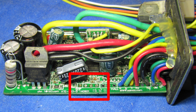
a controller KT36/48SVP, S06S, S09S, S12S from the relevant webshops.
The links are exemplary, of course other sources can be used.
Attention! KT36/48 ZWS types have no phase current sensor mounted, so you can't use the simplified FOC with them! On most boards you can retrofit such a sensor though.
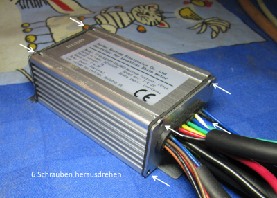
- Unscrew the four screws on the end face with the cable outlet and the two top screws on the opposite side. Carefully lift off the cover with the inscription.
-
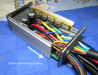
Unscrew the three screws (fastening the FETs) on the narrow longitudinal side.
-
remove the controller board carefully with the cable cover
-
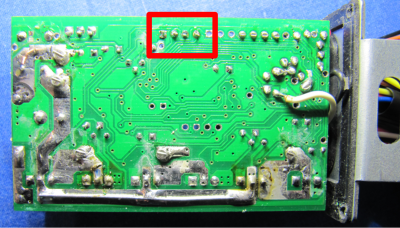
Use a pointed object to carefully insert an additional hole into the rubber sleeve of the cable outlet. Carefully ensure that no other cable is damaged.
-
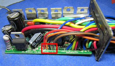
Thread the cable ends of the PCB connector from the outside through the pierced hole.
-
insert the cable ends into the soldering eyes of the board and solder them in. Make sure that the cable ends do not protrude further out of the PCB than the existing cables, if necessary pinch off excess length with string cutter. Write down which cable colour was soldered to which connection! It is recommended to solder red on 5V and black on GND, as long as these colours are available on the PCB connector.
-
Carefully push the PCB back into the housing, making sure that the insulation strips are in the right place again.
-
Screw the housing together again. Start with the three fixing screws of the FETs, on which you can despair.....; -)
-
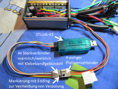
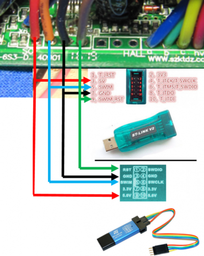
Make the connection between the controller and the STLink-V2 using the jumpers.
- For some extra functions, you can solder a wire to terminal "X4" and rout it outwards.
A few steps are required to set up the software. But they should also be feasible for inexperienced computer users: -).
-
download and install Java Runtime Environment
-
download SDCC 3.7.x and install it. Choose one of the recent .exe files, not the link in the green button. Make sure, that the checkbox for setting the path is activated.
-
download or clone the Github repository and unpack it to the desired location, in the simplest case directly to C: \
-
download and install ST Visual Development with the default settings. If the path to the file "STVP_CmdLine.exe" is different from "C:\Program Files (x86)\STMicroelectronics\st_toolset\stvp", you have to edit the first line of the "Start_Compiling.bat" and the "WriteOptionBytes.bat" according to your path (rightclick on the .bat-file -->edit) . To download the software you have to enter an e-mail address, to which the download link will be sent. This has not caused any unwanted advertising mails/newsletters for me.
-
optional for brave people who want to add more features themselves: Download Eclipse for C++ Developers and unzip it to the desired location. There is no installer here, just double-click on eclipse.exe.
For easy handling of the firmware there is a graphical tool based on Java.
In this tool you can set all relevant parameters and flash them to the controller.
Removing the write protection from the controller is also done with a mouse click. Attention! If this function is selected, the original Kunteng firmware will be irretrievably deleted! Please make sure to find out the correct phase and Hall sensor assignment on the complete system with the original firmware before deleting. This makes sure, that the controller and the motor work together in principle. Still it can be necessary to swap the wires after flashing the firmware to a different combination. If the motor doesn't start properly with the custom firmware (turns not or only very slowly with noise and high current) try to find the right combination by trial and error. Also test the other peripheral devices such as throttle, PAS and brake lever for correct function on the entire system beforehand!
The tool is started by double-clicking on "OSEC Parameter Configurator. jar" in the project directory.
-
Number of PAS magnets: Number of magnets in the PAS disk. Required for correct calculation of the cadence
-
Wheel circumference: Wheel circumference in millimetres, is required to calculate the speed. The setting in the display is ignored.
-
PAS Timeout: Time to stop motor after stopping pedaling. Value in 64µs for Motor Speed = Normal, 48µs for Motor Speed = High. Calculation example: 3125*0,000064s = 0,2s
-
Speed Limit (km/h): Self-explanatory
-
Assist factor: Factor for calculating the torque sensor mode support. Calibration factors of the measurement chain are summarized here. Greater value: More support with equal human performance. The value is internally offset with the percentage defined in the Assist level.
-
Throttle min: Voltage at closed throttle or torque signal. Required for adapting the throttle signal to full 8bit resolution of the PWM value. Conversion: 0V corresponds to 0, 5V corresponds to 255 (8bit resolution of the AD converter)
-
Throttle max: Voltage at full throttle or full deflection of the torque signal, explanation analogous to Throttle min
-
Battery Current max: maximum battery current. Calculation: Value = desired current in ampere multiplied by the value from field Battery Current cal a minus value from field Battery Current cal b. Example with the default values for limiting to 15A: 15A *10 - (-312) = 462
-
Phase Current max: maximum phase current. Calculation like Battery Current max. The phase current is derived from the formula phase current = battery current / duty cycle internally.
-
Regen Current max: maximum recuperation current. Calculation analogous to Battery Current calculate max. desired current as negative value.
-
Undervoltage limit: Undervoltage cutoff value. Calculation: Value in volts times 3.7. example: 34.3V * 3.7 = 127
-
Motor specific angle: with this value the timing of the motor control can be changed. As a result, manufacturing inaccuracies of the Hall sensor positions in the motor can be compensated. Only change if the motor starts badly.
-
Battery Current cal a: Factor a in the calibration function Current in ampere = a * ADC value + b Required for internal calculation of the current from the 10bit ADC value. Only needs to be changed if the calibration obviously does not fit with the preset values.
-
Temperature cal a: Factor a in the calibration function temperature in °C = a * ADC value + b. For temperature calculation from external sensor connected to pad X4 and GND. Temperature is shown in the LCD3 but not processed to reduce power if temperature is getting to high actually.
-
Temperature cal b: Factor b in the calibration function temperature in °C = a * ADC value + b. Default values are for a KTY84 sensor.
-
Gear ratio: Ratio of electrical revolutions to wheel revolutions. The value is half the value of P1 for Kunteng displays, since P1 uses the number of magnets and for Gear Ratio, we need the number of pole pairs. Only needed if option Speed sensor = Internal.
-
Assist Level 1: Support factor level 1 in torque sensor and torque simulation mode. Calculated as a percentage with the assist factor / maximum battery current
-
Assist Level 2 to Assist Level 5: see Assist Level 1
-
Morse-time 1: Is the first time of the morse code in 1/50s. The value 50 means one second. The cheat works like this: Hold the brake lever for cheat time 1, then release it for the duration of cheat time 2, then pull it again for cheat time 3, then release it again. For step 1 with a value of 50, the release of the brake lever is recognized as valid for a period of 1 to 1.5 seconds after pulling and continues with step 2. If the lever is released too early or too late, the whole procedure is reset and you have to start all over again. Currently the user does not get any feedback on whether the cheat has been activated.
-
Morse-time 2 and Morse-time 3: see Morse-time 1
-
Ramp end: Duration of time between two PAS pulses in 64µs (48µs for Motor speed = High), which belongs to the desired limit cadence in torque simulation mode. Value = 60/ ((Wish cadence in 1/min)Number of PAS magnets64µs). Example calculation for a limit cadence of 60/min: 60/ (60160,000064)=977
-
GAIN P: Proportional factor of the PI controller. The higher the value is selected, the higher the risk, that the control starts oszillating.
-
GAIN I: Integral factor of the PI controller. The smaller the value, the smoother the control runs into the setpoint. Both gain values must be written with a dot as a decimal separator.
-
Serial cells: Number of battery cells connected in series. For 36V systems normally "10", for 24V systems "7", this information is required for the correct display of the bars in the LCD3-display.
-
Motor Speed -> Normal: PWM frequency 15.625 kHZ, sufficient for direct drive and most hub and mid-engines.
-
Motor Speed -> High: PWM frequency 20.833 kHz, for very fast rotating motors
-
Display Type -> None: No display support. However, parameters (currently fixed in the code) can be sent to a laptop or to the smartphone via a Bluetooth module. To change the output parameters, see the tab "5.Programming new features". Without display, support level 3 is preset. Connect Rx of the display connector to GND (yellow to black) if you don't want to sent any data to the controller, even if you use Tx for diagnostics.
-
Display Type -> Kingmeter J-LCD: Support of the Kingmeter J-LCD and the Lishui Forerider-App. At present, only the normal operating mode works, the programming mode of the display and the app are not supported.
-
Display Type -> KT-LCD3: Support of Kunteng LCD3, only the speed and wheel size are used. All other settings are currently without function.
-
Display Type -> Diagnostics: If this option is activated, the display protocol is not sent via UART, but some selected internal variables. These five values are sent as default:
- duty cycle of the PWM (0... 255)
- ERPS
- battery current (10bit AD converter value)
- battery voltage (10bit AD converter value)
- advance angle
-
Ride Mode -> Throttle: Operation with throttle handle without PAS detection, the motor runs even without pedaling
-
Ride Mode -> Throttle and PAS: Operation with throttle handle with PAS detection, motor only runs when pedaling.
-
Ride Mode -> Torque Sensor: Motor control proportional to the driver's performance. Power of the motor = factor * torque at the crank * cadence It follows from this that there is no support at starting up, since the cadence is still zero here.
-
Ride Mode -> Torque Simulation: Motor current is increased proportionally to the cadence to the predefined current stage at the limit cadence defined in Ramp End. If the recent cadence is faster than the limit cadence, the current stage is held.
-
Speed sensor -> Internal: Speed is calculated from the motor commutation. No speed is displayed here for motors with freewheel function when the motor is at standstill.
-
Speed sensor -> External: Speed is calculated from external sensor signal. The speed is always correctly displayed here, even when the motor is at a standstill and in the case of middrive motors.
-
PAS direction –> Right/Left: Switch the direction, if motor runs only while pedaling in reverse
-
PAS threshold: Threshold for direction detection from the PAS signal. The value should be the arithmetic mean of the reciprocal of the duty cycle of the PAS-signal during forward and reverse rotation. The appropriate value can be determined by trial and error or by looking at the displayed values at turning the pedals forwards and backwards in "Diagnostics" mode. The preset 1.7 was determined for a simple PAS with 8 magnets.
-
Regen --> linear: linear regen via an analog voltage on pad X4, you can use an additional thumb throttle for example
-
Regen --> digital: regen is activated by the brake lever switch
Write Configuration button: The set parameters are written to the file "config. h" and the compilation of the code and then the flash process is started. The controller must be connected to the STLink-V2. Flashing can be observed by the blinking LED in the STLink-V2.
Write Option Bytes button: Remove the write protection of a new controller. Attention, this function deletes the original firmware of Kunteng and cannot be undone! This function only has to be executed once per controller.
You have to edit the path to your STVP and SDCC installation in the .bat / sh files, if not installed directly in C:, to use the Java-tool / the .bat files
- Just double click on "Start_Compiling.bat"
- or hit "Run" Button on Eclipse
- or hit "Write Configuration" Button on the OSEC Parameter Configurator
- clean the previous built files: $ make -f Makefile_linux clean
- build the firmware as main.bin and main.elf: $ make -f Makefile_linux
There is always things to improve, don't hesitate to get involved if you have improvements in mind.
The current code has basic functions for kingmeter J-LCD and LCD3/5 implemented, which also allows the use of the Lishui Bluetooth module and the corresponding Forerider app. An Android App is in development so that a cheap Phone might be used as a display alternative in the future.


