GithubHelp home page GithubHelp logo

hugen79 / nanovna-h Goto Github PK

View Code? Open in Web Editor NEW
506.0 75.0 125.0 12.5 MB

NanoVNA-H based on edy555 design, provides effective measurements up to 1.5GHz.

Home Page: http://nanovna.com/

Makefile 0.25% C 99.69% Shell 0.01% Tcl 0.06%

nanovna-h's Introduction

NanoVNA - Very tiny handheld Vector Network Analyzer

DIY的矢量网络分析仪,原项目地址https://github.com/ttrftech/NanoVNA,修改了部分电路,增加了电池管理电路,重新设计了PCB。改进了的频率算法,可以利用si5351的奇次谐波扩展支持到900MHz的测量频率,设计了金属屏蔽片,可以减少外部干扰提高测量精度,si5351直接输出的50K-300MHz频段提供优于70dB的动态。最新版本的rev3.5版本硬件可以扩展到1.5GHz以上,更多信息请参考NanoVNA.com

We remade NanoVNA based on edy555 (https://github.com/ttrftech/NanoVNA) , but modified some circuits, added battery management circuits, and redesigned the PCB. The improved frequency algorithm can use the odd harmonic extension of si5351 to support the measurement frequency up to 900MHz. The metal shield is designed to reduce the external interference and improve the measurement accuracy. The 50k-300MHz frequency range of the si5351 direct output provides better than 70dB dynamic. The latest version of rev3.5 hardware can be extended to above 1.5GHz. For more information, please refer to NanoVNA.com .

编译

Build firmware

NanoVNA-H TARGET = F072

NanoVNA-H4 TARGET = F303

It is recommended to compile with gcc-arm-none-eabi 8, and exceptions may occur with other versions of the compiler. Please sync the CibiOS submodule before compiling.

$ git submodule update --init --recursive

MacOSX

Install cross tools and firmware updating tool.

$ brew tap px4/px4
$ brew install gcc-arm-none-eabi-80
$ brew install dfu-util

Linux

Download arm cross tools from here.

$ wget https://developer.arm.com/-/media/Files/downloads/gnu-rm/8-2018q4/gcc-arm-none-eabi-8-2018-q4-major-linux.tar.bz2
$ sudo tar xfj -C /usr/local gcc-arm-none-eabi-8-2018-q4-major-linux.tar.bz2
$ PATH=/usr/local/gcc-arm-none-eabi-8-2018-q4-major/bin:$PATH
$ sudo apt install -y dfu-util
$ make

Windows

Follow these instructionsto install gnu-mcu-eclipse.

Existing Code as Makefile Projiect. Project > Properties > C/C++ Build > Setting: Confirm that Toolchains is "GNU MCU Eclipse ARM Embedded GCC (arm-none-eabi-gcc)"

Project > Properties > C/C++ Build > Tool Chain Editor:

Current toolchain: ARM Cross GCC
Current builder: Gnu Make Builder

Build Project.

当前版本源码基于**DiSlord**的源码修改,如果编译失败,请参考NanoVNA-D的说明

The source code of the current version is based on the source code modification of DiSlord. If the compilation fails, please refer to [NanoVNA-D](https://github.com/DiSlord/NanoVNA- D) Description

DiSlord/NanoVNA-D#1 (comment)

Debug use Eclipse + cmsis-dap +openocd

Debugger Configurations > GBD OpenOCD Debugging, Double click to create a new setting, Select “Debugger“ label, add config option.

-f NanoVNA_DAP.cfg

感谢edy555创建了这个项目,所有软件版权归edy555所有。 Thanks to edy555 for creating this project, all software copyrights are owned by edy555 https://github.com/ttrftech/NanoVNA; 感谢cho45对项目做出重大改进。 Thanks to cho45 for making major improvements to the project. https://github.com/cho45/NanoVNA

感谢DiSlord对项目的持续改进。 Thanks to DiSlord for continuous improvement of the project https://github.com/DiSlord/NanoVNA-D.

以下为原项目自述

The following is the original project readme

About

NanoVNA is very tiny handheld Vector Network Analyzer (VNA). It is standalone with lcd display, portable device with battery. This project aim to provide an RF gadget but useful instrument for enthusiast.

This repository contains source of NanoVNA firmware.

Prepare ARM Cross Tools

UPDATE: Recent gcc version works to build NanoVNA, no need old version.

MacOSX

Install cross tools and firmware updating tool.

$ brew tap px4/px4
$ brew install gcc-arm-none-eabi-80
$ brew install dfu-util

Linux (ubuntu)

Download arm cross tools from here.

$ wget https://developer.arm.com/-/media/Files/downloads/gnu-rm/8-2018q4/gcc-arm-none-eabi-8-2018-q4-major-linux.tar.bz2
$ sudo tar xfj -C /usr/local gcc-arm-none-eabi-8-2018-q4-major-linux.tar.bz2
$ PATH=/usr/local/gcc-arm-none-eabi-8-2018-q4-major/bin:$PATH
$ sudo apt install -y dfu-util

Fetch source code

Fetch source and submodule.

$ git clone https://github.com/ttrftech/NanoVNA.git
$ cd NanoVNA
$ git submodule update --init --recursive

Build

Just make in the directory.

$ make

Build firmware using docker

Using this docker image without installing arm toolchain.

$ cd NanoVNA
$ docker run -it --rm -v $(PWD):/work edy555/arm-embedded:8.2 make

Flash firmware

First, make device enter DFU mode by one of following methods.

  • Jumper BOOT0 pin at powering device
  • Select menu Config->DFU (needs recent firmware)

Then, flash firmware using dfu-util via USB.

$ dfu-util -d 0483:df11 -a 0 -s 0x08000000:leave -D build/ch.bin

Or simply use make.

$ make flash

Control from PC

See python directory.

Note

Hardware design material is disclosed to prevent bad quality clone. Please let me know if you would have your own unit.

Reference

Credit

Contributors

nanovna-h's People

Contributors

czietz avatar hugen79 avatar

Stargazers

 avatar  avatar  avatar  avatar  avatar  avatar  avatar  avatar  avatar  avatar  avatar  avatar  avatar  avatar  avatar  avatar  avatar  avatar  avatar  avatar  avatar  avatar  avatar  avatar  avatar  avatar  avatar  avatar  avatar  avatar  avatar  avatar  avatar  avatar  avatar  avatar  avatar  avatar  avatar  avatar  avatar  avatar  avatar  avatar  avatar  avatar  avatar  avatar  avatar  avatar  avatar  avatar  avatar  avatar  avatar  avatar  avatar  avatar  avatar  avatar  avatar  avatar  avatar  avatar  avatar  avatar  avatar  avatar  avatar  avatar  avatar  avatar  avatar  avatar  avatar  avatar  avatar  avatar  avatar  avatar  avatar  avatar  avatar  avatar  avatar  avatar  avatar  avatar  avatar  avatar  avatar  avatar  avatar  avatar  avatar  avatar  avatar  avatar  avatar  avatar

Watchers

 avatar  avatar  avatar  avatar  avatar  avatar  avatar  avatar  avatar  avatar  avatar  avatar  avatar  avatar  avatar  avatar  avatar  avatar  avatar  avatar  avatar  avatar  avatar  avatar  avatar  avatar  avatar  avatar  avatar  avatar  avatar  avatar  avatar  avatar  avatar  avatar  avatar  avatar  avatar  avatar  avatar  avatar  avatar  avatar  avatar  avatar  avatar  avatar  avatar  avatar  avatar  avatar  avatar  avatar  avatar  avatar  avatar  avatar  avatar  avatar  avatar  avatar  avatar  avatar  avatar  avatar  avatar  avatar  avatar  avatar  avatar  avatar  avatar  avatar  avatar

nanovna-h's Issues

(Reopened) Unexplained behaviour of calibration correction around high concentration of poles and zeros

This issue is intended to be appended to issue #38, that I closed for a mistake and I'm unable to reopen.

Hi DisLord.
I already fixed this while I added the RF switch to the schematic.
I implemented a simple extrapolation algorithm computed on the two closest measured calibration points, instead of the interpolation at the two edge of the band change point.
It works great at 300MHz, but the IS_HARMONIC _MODE macro fails to detect the other band changes (the 900MHz) probably because it has been forgotten to be changed when the instrument has been extended above 900MHz.

Anyways this is my the code for the moment that works at 300MHz:

Place this in the define area for enabling this new interpolation/extrapolation algorithm:
#define __NewBandChangeInterpolation__ 1

Place this into static void cal_interpolate(int s):


#if __NewBandChangeInterpolation__ == 1
          float k1 = (float)(f - src->_frequencies[j])
                          / (src->_frequencies[j+1] - src->_frequencies[j]);

          // avoid glitch between freqs in different harmonics mode
          if (IS_HARMONIC_MODE(src->_frequencies[j]) != IS_HARMONIC_MODE(src->_frequencies[j+1])) {
              int m;
        	  if (IS_HARMONIC_MODE(f)){
				  float k0 = 2 - k1;
				  k1 = k1 - 1;
				  for (eterm = 0; eterm < 5; eterm++) {
					cal_data[eterm][i][0] = src->_cal_data[eterm][j+1][0] * k0 + src->_cal_data[eterm][j+2][0] * k1;
					cal_data[eterm][i][1] = src->_cal_data[eterm][j+1][1] * k0 + src->_cal_data[eterm][j+2][1] * k1;
				  }
        	  }
        	  else{
				  float k0 = - k1;
				  k1 = k1 + 1;
				  if (j == 0){
					  m = j;
				  }
				  else{
					  m = j - 1;
				  }
				  for (eterm = 0; eterm < 5; eterm++) {
					cal_data[eterm][i][0] = src->_cal_data[eterm][m][0] * k0 + src->_cal_data[eterm][j][0] * k1;
					cal_data[eterm][i][1] = src->_cal_data[eterm][m][1] * k0 + src->_cal_data[eterm][j][1] * k1;
				  }
        	  }
          }
          else{
              float k0 = 1.0 - k1;
              for (eterm = 0; eterm < 5; eterm++) {
                cal_data[eterm][i][0] = src->_cal_data[eterm][j][0] * k0 + src->_cal_data[eterm][j+1][0] * k1;
                cal_data[eterm][i][1] = src->_cal_data[eterm][j][1] * k0 + src->_cal_data[eterm][j+1][1] * k1;
              }
          }

          break;

#else
          float k1 = (float)(f - src->_frequencies[j])
                          / (src->_frequencies[j+1] - src->_frequencies[j]);

          // avoid glitch between freqs in different harmonics mode
          if (IS_HARMONIC_MODE(src->_frequencies[j]) != IS_HARMONIC_MODE(src->_frequencies[j+1])) {
            // assume f[j] < f[j+1]
            k1 = IS_HARMONIC_MODE(f) ? 1.0 : 0.0;
          }

          float k0 = 1.0 - k1;
          for (eterm = 0; eterm < 5; eterm++) {
            cal_data[eterm][i][0] = src->_cal_data[eterm][j][0] * k0 + src->_cal_data[eterm][j+1][0] * k1;
            cal_data[eterm][i][1] = src->_cal_data[eterm][j][1] * k0 + src->_cal_data[eterm][j+1][1] * k1;
          }
          break;
#endif

instead of the current:

          float k1 = (float)(f - src->_frequencies[j])
                          / (src->_frequencies[j+1] - src->_frequencies[j]);

          // avoid glitch between freqs in different harmonics mode
          if (IS_HARMONIC_MODE(src->_frequencies[j]) != IS_HARMONIC_MODE(src->_frequencies[j+1])) {
            // assume f[j] < f[j+1]
            k1 = IS_HARMONIC_MODE(f) ? 1.0 : 0.0;
          }

          float k0 = 1.0 - k1;
          for (eterm = 0; eterm < 5; eterm++) {
            cal_data[eterm][i][0] = src->_cal_data[eterm][j][0] * k0 + src->_cal_data[eterm][j+1][0] * k1;
            cal_data[eterm][i][1] = src->_cal_data[eterm][j][1] * k0 + src->_cal_data[eterm][j+1][1] * k1;
          }
          break;

Now I'm working at office and I'll try fix it the IS_HARMONIC macro in the next days.
Instead, in case you'll fix it before, please let me know, thank you.

Massimo - IK1IZA

Add option to unlock 1.5GHz till 2.1GHz range for those that know what they are doing

As the performance of the v3.4 HW is so much better it makes sense to offer an option to unlock the 1.5GHz till 2.1GHz range.
The measurement results above 1.5GHz have more noise but are usable.
I tested a 1.8GHz low pass filter and a 2GHz cavity filter. Both measured as they should but with some noise.
Could there be a menu option to unlock above 1.5GHz?

70cm SWR gives different value than previous versions

I updated the firmware of my NanoVNA-H to the recent version 1.0.45. When I had checked the NanoVNA vs a dummy load on previous versions, I got ~1.4-1.5 SWR on 70 cm (440 to 450Mhz) and it was relatively flat across the entire range.

I updated the firmware and then ran clearconfig, and re-calibrated.

With the new firmware, the SWR at 440 is around 1.75 and climbs thru the range to over 2.

The 2m SWR measurement is unchanged at ~1.1.

Not sure what would cause this. I even went back to the previous version (0.4.5-4), ran clearconfig, re-calibrated, checked it, got similar answers to previous tests, installed the newest version again, clearconfig, re-calibrated, and again got the 1.7+ reading on 70cm. I used the same coax for all 4 tests (I tested 2m again as well for completeness; it was unchanged) so I don't think it's my setup.

Any help is appreciated. Thanks, Bruce

Please share schematic V3.1

Could you please share schematic for PCB rev V3.1?
The schematic in the doc folder is V3.3, but my NanoVNA-H has PCB V3.1.
Thanks

Proposal: add suffix to your product name (eg. NanoVNA-H)

Hi hugen,

I'm an original developer of NanoVNA.
When I knew that you made the clone of my project, I very surprised that you made PCB from schematics, and as an enthusiast, I felt pleased with your challenges such as frequency range expansion and your original pc software.

However, I was annoyed that you sell your clone without any prior notice to me. Though I had a plan to forge and sell my product, it becomes difficult.
Furthermore, your act cause that your design material was stolen by other clone makers, and quite many units were sold in aliex, ebay and also amazon. Those include worse clone as you say. This is a worrying state of affairs I think, and you might agree.

To distinguish any unexpected clones, I propose that you should change your product name by adding a suffix such as NanoVNA-H from your name, and it should be shown in the market and printed on your product.
And also I'd like to publish the name of qualified products, so customers become able to avoid worse clone.

I hope you think about this issue seriously.
Regards,

NanoVNA-H4 center frequency change above 1 GHz

hugen please see my review of the NanoVNA-H4 at https://groups.io/g/nanovna-users/message/10012 . I encountered the lock-up when trying to set the center frequency in the 1 - 1.5 GHZ range. Another member, https://groups.io/g/nanovna-users/message/10024 , also confirmed his NanoVNA-H4 locked up when setting the center frequency in the same range.

Multiple users have also encountered a QA problem, https://groups.io/g/nanovna-users/message/9914 , where the USB-C case opening is too small and the cable will not fit. My unit was fine but a few members have had to enlarge the opening by hand.

  • Herb

Memory indication in use

When "save" is selected the memory in use is highlighted (after calibration for example).
Makes it easy to remember and save the calibrate in the correct memory.
Thanks for the work :)

shell command marker vs touch panel STIMULUS

Change START from 50k to 10k and STOP from 900M to 1200M by touch screen,
then by USB:
ch> version
0.4.0-3-ge04d3af
ch> marker
1 0 50000
ch> marker 1 1
ch> marker
1 1 12009900
ch> marker 1 0
ch> marker
1 0 10000

Setting center frequency still wrong computing span

Hi Hugen.
I installed latest version of nanoVNA-H4 but I see that the issue is still there.
Maybe you are unaware of it, because I wrote that in a message about an another issue, (my fault indeed).
Anyways, there is a bug in computing the frequency when setting the center frequency with the span already set to 1.499 990 000GHz. If the center frequency is set with the sum of the center frequency + span/2 greater of 2.147GHz the computation fails and leaves the span as it was before. Anyways this is because a 32 bit signed integer can hold a maximum value of 2^31=2,147,483,648 and during the frequency0 and frequency1 computation, this limit it's overcome.
You should adjust that function to avoid that.

To check this issue, just set [Start] to 10kHz, [Stop] to 1.5GHz and then set [Center] to 1.4GHz.
You should get the right center frequency but the span remains set to 1.499 990 000GHz.

Have a great day.

Massimo

Reference impedance setting

Sometimes I need to measure a 75 ohm system, but 75 ohms shows as 50 ohms on the graphs when I calibrate using a 75 ohm load. Would it be possible to add a setting for impedance in the software, so I can match it to the resistance I use when calibrating?

I understand that anything other than 50 ohms is most likely not optimal for the NanoVNA's hardware, and that it would be batter to use something like impedance converters, but right now I don't need anything too precise and I haven't encountered any big discrepancies when measuring in 75 ohm, other than the displayed values being 2/3 of the actual value.

There could also be a warning when changing the impedance value, that it could make the results less accurate.

Jog L & R switches appear to stop working after touchscreen menu use

I have found a problem with your Oct 9 4-trace release, where I use only the touchscreen and I select CONFIG and then the VERSION menu items and go back up the menu tree to select something else, then back to the version menu and then clear the menu from the screen.
Now, if I try to use the jog switch, I get the menu appear with ENTER but I can no longer get any menu items to highlight.
It appears the switches are being sensed because if I press Enter to bring up the root menu and then press the Right key 7 times, the menu disappears - but nothing was highlighted.
I tried the same menu sequence on QRP's 0.4.3 release and it is OK.
Thanks.
Larry

Cross compiling on a Raspberry Pi...

Hi,

i tried to cross compile the stuff on a Raspberry Pi 3. The toolchain mentioned at "Prepare ARM Cross Tools" can not be used on a RasPi.
But i found a precompiled toolchain for the Raspberry Pi at https://github.com/vanbwodonk/gcc-arm-embedded-build-armhf. This toolchain is more recent (8-2019-q3-update).
Differing from the description there, i used the following lines to install the toolchain:

wget https://github.com/vanbwodonk/gcc-arm-embedded-build-armhf/raw/master/pkg/gcc-arm-none-eabi-8-2019-q3-update-linux-armv7l.tar.bz2
tar -xvf gcc-arm-none-eabi-8-2019-q3-update-linux-armv7l.tar.bz2
sudo cp -r gcc-arm-none-eabi-8-2019-q3-update/* /usr/local/
sudo rm -r gcc-arm-none-eabi-8-2019-q3-update

Additionally i added the following line at the end of ~/.profile:

PATH=/usr/local/usr/local/arm-none-eabi/bin:$PATH

My first attempt fails to get the toolchain work on my Raspbian Stretch (Debian 9) because the toolchain needs glibc 2.28, but Stretch uses 2.24.
So Raspbian Stretch must be updated to Buster (see https://pimylifeup.com/upgrade-raspbian-stretch-to-raspbian-buster/) to get the toolchain work.

After upgrading Raspbian make runs well and the binary was built.

Hope this helps if someone want to cross compile on a RasPi...

Regards, Thorsten

NanoVNA-H4: "scan" console cmd causes display to dim

Sending a scan console command (i.e. "scan 50000 30000000) to the NanoVNA-H4 causes the display to dim. The display stays dim until a "resume" console command sent. I'm pretty sure this interaction between the display and the scan command is unintentional.

This issue has been verified by other NanoVNA-H4 users at [email protected].

  • Herb

My old fixes for NanoVNA-H

Hi after i by NanoVNA-H i begin fix from this firmware.

But not public it, and adaptate to eddy (and continue work on it), but old font fixes still exist

I upload this fixes to my repo https://github.com/DiSlord/NanoVNA-H
Not test, but must work

Possible in future i order nanoVNA-H4 and try work on it

White screen of NanoVNA-H 3.4

Good time to all who read. I purchased a NanoVNA-H V. 3.4 and got a white screen when I turned it on for the first time. The second time the device was turned on, I thought it was something with the firmware and flashed it to a more recent one. But even after that, it periodically turned on with a white screen. Flashed firmware for the H version. Now the device turns on only with a white screen. The operation led is blinking, but there is no image. I switched to DFU mode by shorting the contacts on the Board. NanoVNA Saver with the device works, so the processor is whole. Is the TLV320 faulty? How do I make the screen work?

CH1 port not pure 50 ohm

The CH1 input impedance shows a substantial reactive part that hampers measuring certain components, mostly two port devices that are sensitive the the output impedance they see.
This is most obvious in the T-Check
Here you see the T-Check performed with only a coax, a Tee and an extra 50ohm resistor
http://athome.kaashoek.com/public/eevblog/NanoTeeCheck.JPG

When you put a 10dB attenuator at the input of CH1 and redo the full calibration and then do the T-Check you get this:
http://athome.kaashoek.com/public/nanoVNA/T-check.PNG
Much improved.
So having a well defined attenuator at the input of CH1 could give substantial improvements because it removes the reactive components of the impedance.

Selector control acts flaky....

I've read several reviews complaining about the same problem I have. The issue is either that when you press one of the three selector switches, nothing happens. I have to try over and over again. It seems kind of like it depends on what the VNA is doing. It is possible the selector hardware is flaky, but I suspect the software. I'm kind of wondering if the software not monitoring the switch constantly. Could it be made to trigger an interrupt, so button presses are not missed?

I haven't really looked into the source code yet, but it appears you made the change from touch screen to selector switch, so I thought I'd ask. Any ideas?

Thanks,
Rob

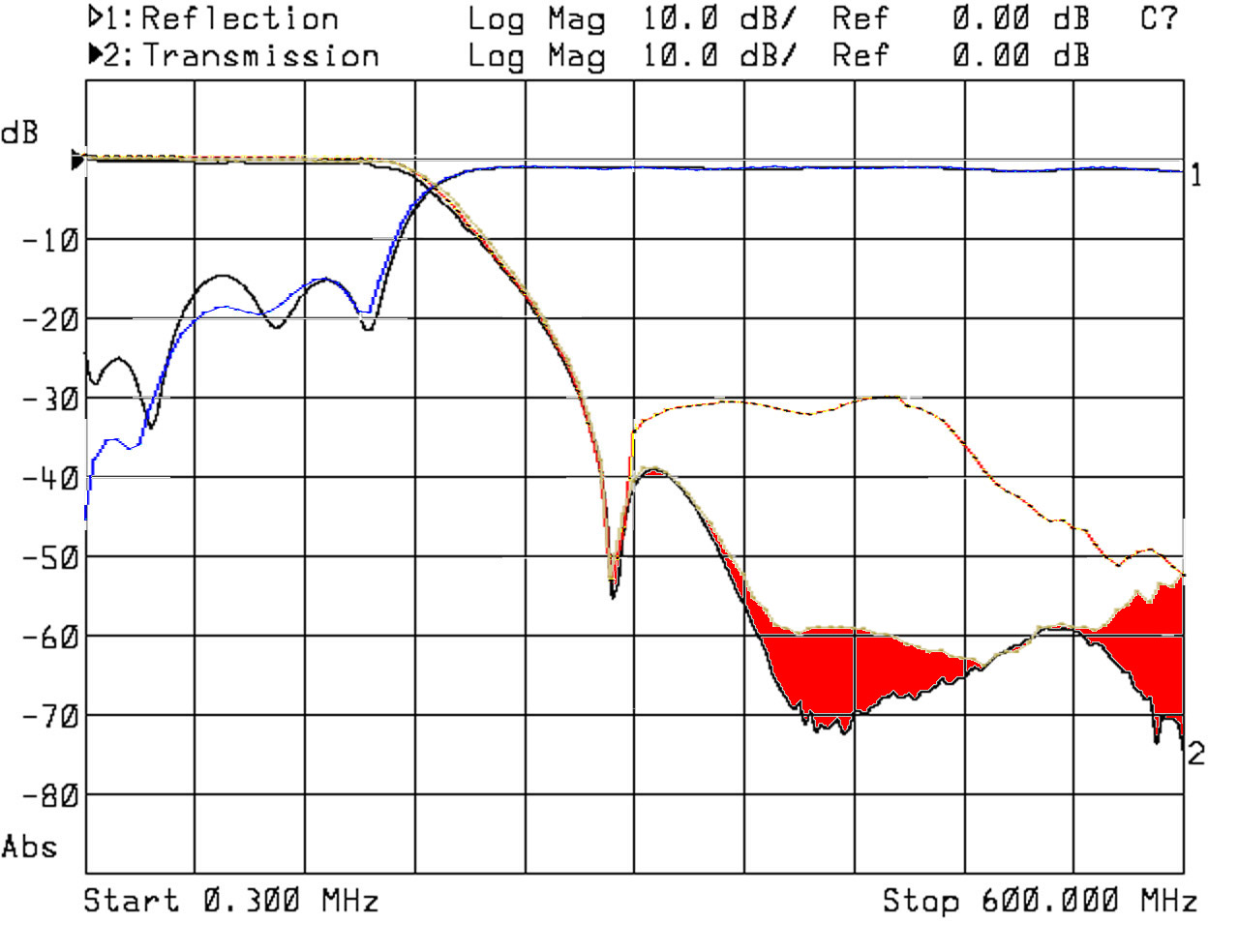
(Fixed) Hardware mods to get fixed the loss of dynamic of CH1 in the harmonics mode

Hi Hugen,
here I publish my mods to almost completely fix the loss of dynamic above 300MHz when the DUT is a LPF tuned below but closed to 300MHz such as VHF/UHF duplexers.
The mods on my prototype still have a little loss of dynamic, but make the instrument useful.
Here are the graph before and after the "cure".
Before:
Test 300kHz-600MHz
After:
Test 300kHz-600MHz RFsw

The red areas are the remaining dynamic losses.
Above 600MHz I never see any substantial dynamic loss.
The schematics are the followings.
With added 8MHz oscillator for the MCU & DSP:
HPF 300MHz Elliptic 5th Order with Switch
With 2 RF switches:
HPF 300MHz Elliptic 5th Order with 2 Switch
The two solutions are because it has been easier for me to use the inner output power amplifiers enable signal of the Si5351A instead to add an another RF switch (the size of nanoVNA have been a great constraint for fit the prototype PCBs there). This photo explains all:
IMG_20200321_165004
Anyways, the single RF switch version gives the advantage of a stable clock to the MCU & DSP. This because the "arrhythmia" that I seen in the MCLK (that I was believing due to the noises around), it was instead due to the clock interruptions during the band switching. The only reason the system doesn't locks, it's that the inner PLLs of both the chips still produce a clock, even if on a very different frequency.
The contra of the single RF switch solution is that I had to modify the Si5351A settings to get the DUT test frequency from output 1 for frequencies below 300MHz and from output 2 for the frequencies above. This implies that the firmware is no longer compatible with the older hardware setup.
I used the scan LED2 signal (U4-2) to drive the 5th order high pass elliptic filter, but my choice is due just because it was the easiest solution to get a sufficient wide pad to solder the switch(es) control wire in the nanoVNA PCB.
For the firmware development, the U4-2 signal must be set active at 3.3V for the odd harmonics mode and must be set deactive at 0V for the fundamental mode.

I also changed the CH1 front-end configuration as follows:
R22 = 68 ohm 0603 1% resistor
R23 = 0ohm 0603 shunt
R24 = 120ohm 0603 1% resistor
R25 = 22ohm
Note that it has changed form differential to single ended, just because it was a nonsense. The driving signal of the SA612D mixer was in-phase on both sides of R25, so there was no advantages using that configuration. I found this configuration less noisy indeed and best matching the CH1 input port impedance for higher frequencies, that thanks to the higher value of R22 that is the one which influence more the capacitive behaviour of the CH1 input port trought the mixer input capacitance.

By the way, I found a strange stream of pulses on the LED2, which is produced by the macro PULSE into nanoVNA.h and used by function draw_cell() into plot.c.
I think it was some checking signal used during debug that I think it should be removed.

I thought to publish this mod procedure for those who desire to modify their current or the older versions of nanoVNA, but the complexity of it suggested me to avoid it. I had to use a thin SR-047 coaxial line to connect the filter which involves a certain skilness to do it.

Hope this will help you for your next production batch.

Have a great day.

Massimo

Is it normal for the readouts to be this low when uncalibrated?

I have been using the NanoVNA-H for some time now, and I've been wondering this for a while, but never cared about it too much as it worked fine when calibrated. However, recently I bought a S-A-A-2 and it doesn't seem to have this problem when uncalibrated, so I finally decided to ask.

The uncalibrated magnitude measurements for CH0 are about -20 dB when nothing is connected, and for CH1 they're -10 dB when CH0 and CH1 are connected together with coax. This seems oddly low, as in both cases they should be close to 0 dB. I remember that it didn't have this issue out of the box, but it might have been pre-calibrated by the seller, and I did a firmware upgrade shortly after receiving it which most likely removed the original calibration.

This is how it looks like when not calibrated:
IMG_1715

With calibration for comparison:
IMG_1714

Is it normal, or does it mean that it's defective, or a crappy clone? (I didn't buy it from the official alibaba link, but from a local seller here)

Bootup hangs after touchscreen calibration

After flashing ALL_FF to clear memory and then flashing NanoVNA-H__900_aa_20191003.dfu the device will boot every time with no issue.

I then calibrate touchscreen - not issues while device stays on.
If device is turned-off, device hangs at bootup every time only showing version screen.

Re-flashed hugen_900_(1500)_ch_sept-24-19.dfu - no issues with lockup.
Re-flashed NanoVNA-H__900_ch_20191003.dfu version - no problem.

Both 800 & 900 AA versions have same issue BUT 800 version boots up showing TDR time at bottom of display and produces unrecognized USB error on PC - DFU mode works though.

No way to save settings

Hi,

in release NanoVNA-H_AA_20200118.dfu there seems to be no way to SAVE the settings. There is only a button for recall.

Kind regards,
Axel

Modifying frontend for 75 ohm Z0

This is, in a way, a continuation of #42. I have upgraded to SAA2 recently, but I still want to make use of my NanoVNA-H, and I thought of converting it to a 75 ohm VNA. I assume that the bridge resistors have to be replaced, but to what values? Do I have to replace any other parts?
Also, in the code I found several variables declared as float z0 = 50;. I assume that I'd have to change that to float z0 = 75; and compile the firmware? Would I have to change the code in any other way?

Enhancement: Shift AA FW vers freq fields to the left slightly

With reference to the AA version of the firmware, is it possible to shift the STOP and marker freq fields to the left enough to show the 0.1 KHz digit?

The change should not really interfere with the rest of the displayed info and it would allow more accurate 12.5KHz measurements at HF and VHF with the current ref xtal.

Thanks.

Time Domain does not let me set the start/stop intervals

Hello,

Thank you for maintaining the software of this great device!

We have been trying to test cable lengths to calculate velocity factor of an unknown cable. When we set the VNA to 50kHz--900MHz and set CH0 to real mode with a transform of low-pass impulse, I am unable to set the start and stop ranges to zoom into the first 20--50ns to see where the minima is for the reflection. If I set the stop frequency while the transform is turned on, the nanosecond range changes expectantly. If I set the stop frequency to 51kHz it sets the upper range to 65535ns, if I set it to 55kHz it sets it to 16087ns.

I tried this example a second time and got different numbers. The second time I did this the cursor position in the top-right corner shows "1:2147483647Gs 21474". This looks like the base-10 value of a 32-bit signed value of "-1" so maybe something in the code is returning an error that is not being handled. 65535 as noted above could be a similar issue since it is -1 in a 16-bit signed short.

I have seen this problem whether or not I calibrate the device and with and without load/short/open screw-caps on CH1 to mute any noise.

What I would really like to do is zoom into where the cursor is, so a zoom feature would be great. In the absence of the zoom feature, being able to set the time domain graph range in ns would be fine as well.

I am new to the VNA so if this is normal behavior and I am missing something then please let me know what I can do and if you need any more information.

Touchscreen slowly responsive / unwanted menu popups

Hi Hugen,
I experienced that while the nanoVNA touchscreen works great, the nanoVNA-H4 touchscreen is slow in detecting the touches, it needs to keep touching for at least half a second to get the touch detected.

I extended the delay between the driving ports setup and the adc differential input ports from 2 to 20ms and this issue has improved a lot now. Maybe this larger screen has an higher capacitance and need more time to stabilize its output to the right voltage.
The timings correction that I did are into the file "ui.c" function "static int touch_measure_x(void)" and function "static int touch_measure_y(void)" .

I also experienced sporadic unwanted menu popups and sometimes when that happens the sweep is suspended for some seconds, while in the meantime, the touchscreen is working anyways.
I suspect it's detecting some noise because of its wider area compared to the 2.8" touchscreen.

Could you publish the H4 schematic?
Possibly in graphic pdf format,
I tried to read the schematic in the doc directory, but opening that pdf file I can see only few components because of some missing fonts. The graphic pdf version should bypass that issue.

Have a great day.

Massimo

Predefined start/stop frequencies

Please add an option to let the user define start/stop frequencies as memories.
This will be awesome for analyzing ham radio bands.

thanks for a great device!

Unexplained behaviour of calibration correction around high concentration of poles and zeros

Hi Hugen.
I'm working about the odd harmonics loss of dynamic when a LPF filter let pass signal in the fundamental band below 300MHz and cuts in the odd harmonics bands above 300MHz.
I already designed a 5th order elliptic HP filter and modified one nanoVNA to clock the MPU and the DSP with a separate 8MHz oscillator as per your nanoVNA-H4 model, and used the CLK2 output of the Si5351A to drive the HP filter to get a cleaner signal with the fundamentals below the harmonics level when the DUT is checked above the 300MHz limit.
I modified the firmware to get the test signal that drives the DUT directly from CLK1 for frequencies below 300MHz and to get the test signal that drives the DUT from CLK2 passed through the filter for frequencies above.
Now the dynamic improved a lot making the device useful for duplexer testing/tuning.
Doing that I experienced an unexplained (for me) behavior of the calibration function of the S11 plot in the range between 150...350MHz.
Since for the moment I simply paralleled the filtered CLK2 output to CLK1 output, this last is influenced by the HP filter poles and zeros in that range (it's an elliptic filter and in the stop band it has abrupt changes in impedance there). I already planned to put an RF switch to remove this loading issue, but I would point out this issue anyways because it seems that the interpolated correction works bad.

This is the uncorrected plot of that range:
S11uncorrected
While this is the plot of the same range when corrected by the interpolated calibration parameters:
S11corrected
I did the 10kHz... 1.5GHz full span calibration and the marker in the plot are placed in the point of that full band calibration.
My question is:
how could the calibrated plot showing those almost parabolic interpolation between two consecutive calibration points?
I also can't explain why that red marker is so high, since this is a calibration point computed exactly with the very same dummy load used for the plot. Anyways, how could the S11 between two successive calibration points at lower RL have an higher RL?
This happens only when the DUT is well matched, in case of S11 close to 0dB this issue disappear little by little as the 0dB line is approached.

Do you have any idea about this?

Have a great day.

Massimo - IK1IZA

recipe for target 'build' failed

I am getting this error when running "make" .

I am not sure what is customary to fix it here.
Is it OK to just report it?

Description Resource Path Location Type
recipe for target 'build' failed rules.mk /NanoVNA-H/ChibiOS/os/common/startup/ARMCMx/compilers/GCC line 171 C/C++ Problem
recipe for target 'build/obj' failed rules.mk /NanoVNA-H/ChibiOS/os/common/startup/ARMCMx/compilers/GCC line 178 C/C++ Problem

$(BUILDDIR):
ifneq ($(USE_VERBOSE_COMPILE),yes)
@echo Compiler Options
@echo $(CC) -c $(CFLAGS) -I. $(IINCDIR) main.c -o main.o
@echo
endif
@mkdir -p $(BUILDDIR)

$(OBJDIR):
@mkdir -p $(OBJDIR)

Just FYI C11 "problem" add -std=gnu11 to "makeflie" compiler options

Current release, as of 11/18/2019, has a same issue with C11 complier as NanoVNA did.
Instead of patching all problem occurrences - about 10 or so, I choose to follow "make" suggestion and added , cheap hack,

Compiler options here.

added -std=gnu11

ifeq ($(USE_OPT),)
USE_OPT = -std=gnu11 -O2 -ggdb -fomit-frame-pointer -falign-functions=16 --specs=nano.specs -fstack-usage
endif

UART connection using NanoVNA-H v3.4 with UARt pins (VDD, TX, RX, GND) available on PCB.

Hi Hugen,
I am not sure if this is the best place to raise this issue. What would be the best and easiest way to access NanoVNA data via UART?
Does the latest firmware accommodate UART connection? Is there a guide to the commands and other resources for UART communication?
Any help in this matter would be highly appreciated, Hugen

Thank you

Kind regards
Advaith

Add Impedance /Z/ to display/format menu

Hello,
I'm just asking whether it would be possible to add to the NanoVNA menu the "absolute impedance" /Z/ as well, rather than only resistance (real and imag) separately.
Real and Imag part is important, for sure, but for some measurements it would simplify to also display /Z/ as well and not having to use Pythagoras every time.

I'm using standard 2.8" NaonVNA primarily for mesuring impedances of ferrites in S0 reflection mode. works perfect !

Thanks a lot for all the SW/FW/HW work in the past !!!
Ulrich

How to switch to .. 1.5Ghz?

Downloaded the latest version from "Releases" and the screen still shows 900Mhz max.
How to extend the range? Do I need to compile from the source for that?
Thank you!

tlv320aic3204 driver

Hi, I found there is a difference in the tlv320aic3204 driver in comparison with edy555 version:

Here is original edy555 code:

    I2CWrite(AIC3204_ADDR, 0x3b, 0); /* Unmute Left MICPGA, Gain selection of 32dB to make channel gain 0dB */
    I2CWrite(AIC3204_ADDR, 0x3c, 0); /* Unmute Right MICPGA, Gain selection of 32dB to make channel gain 0dB */

Here is your code:

    I2CWrite(AIC3204_ADDR, 0x3b, 5); /* Unmute Left MICPGA, Gain selection of 32dB to make channel gain 2.5dB */
    I2CWrite(AIC3204_ADDR, 0x3c, 5); /* Unmute Right MICPGA, Gain selection of 32dB to make channel gain 2.5dB */

Could you please explain what is the reason for this?
Thanks

Noise improvements.

I improved the noise adding few caps to the Silicon Labs clock generator chip and now the standalone instrument is fully working up to 1.5GHz with only a very little residual noise above 1.4GHz that it is appreciable in the Smith chart only.
I still have some issue with the PC communication because of the battery charger that disturbs the clock. I already thought a solution for this too, but I'm waiting for the sot23 P-MOSfet, to check if it works as thought. Once I fixed it I'll publish the "how to" of the whole hardware fixing.
In the meantime I have a couple of desiderata to your code.

  1. the flashing LED 2 is very noisy and useless. It's much better to keep it off, if your intention was to give a pace indicator, I suggest you to implement it as a virtual indicator somewhere on the LCD screen (I currently removed its limiting resistor to keep it off).
  2. Since there is still a little noise above 1.4GHz, It would be great if the calibration was done not by one acquisition of the raw data per calibration step as it is now. It should be better if you get more scans of the raw data and average them to get the correction coefficients averaged on more scans (say 10 scans, for example). This will take a little more time during the single calibration steps, but it should warrant that the noise is corrected on its averaged value and not randomly on the instantaneous values acquired during the single scan.
    Have a great day.
    Massimo

PPM offset in config menu

Updated to: NanoVNA-H_20210130.dfu
10MHz hc49 xtal test reads as 9.997225MHz

Can we use a GPSDO 10MHz reference to add the ppm offset config into the nanoVNA-H menus?
Would seem kind of odd to have to have to flash a custom compiled firmware after warm up, as some are suggesting.

A "cal ppm err @10MHz" option would be stellar ;-)

trace command hung

qrp73/NanoVNA-Q#16
Same issue appeared latest(f6f948b) NanoVNA-H too.

I using "empty trace" command for identify current trace status and scale in my script.
But it will hung occasionally.
I found the only way to remove this issue, Manually reconfigure traces or simply disable unsued trace slot( trace x off ) before send "empty trace". Similar issues on marker too.

Another issue I found was...

  1. Set sweep range to full span 10e3 ~ 1.5e9 / calibrate off / Nothing connected CH0/CH1.
  2. trace all off -> marker 1...4 off -> pause (Blank screen / LED steady - For fast fetch)
  3. Python loop scan&data 0..1 -> Join&save s2p touchstone via scikit-rf
    Exported every data 0...1 and sp2 files was exactly same.

But data is different with sweep&trace 0..1 enabled.( +4 ~ +20 dB point appeared at CH0 logmag )
NanoVNA requires at least one activated trace for get valid data?

Always appreciate your contribution.

NanoVNA-H white screen after installing NanoVNA-H4_20200221

First time every updating the firmware on this. I checked the version message which indicated that my unit was running the -H version and pointed me to this GitHub. I downloaded NanoVNA-H4_20200221.bin from here:

https://github.com/hugen79/NanoVNA-H/releases

Unfortunately on completion of the firmware update my NanoVNA booted to a white screen.
Mine is the -H version and I am updating from a PC running Linux Mint 19.2 so I used the instructions from here:

https://nt7s.com/2019/11/updating-the-nanovna-firmware/

Also here:

https://oristopo.github.io/nVhelp/

Used the following command line:

dfu-util -d 0483:df11 -a 0 -s 0x08000000:leave -D NanoVNA-H4_20200221.bin

My screen came up with a white and blank and nothing else happened even after a wait of a few minutes. No menu, no control functions. Nothing. I then tried bridging the link to get into DFU mode, turned the NanoVNA off then on but the white screen persisted. After a bit of a panic moment I decided to just try uploading the firmware anyway and to my surprise the firmware upload worked, it was just that the display was not telling me that the NanoVNA was in DFU mode. Uploading the same firmware resulted in a white screen again, so I tried the ch.dfu firmware from edy55. This uploaded and booted fine, except my SWR readings seemed to be incorrect (yes I did calibrate).

After a bit of further searching, I noticed that in the previous releases of your firmware (18th January) included an "antena analyser" or "AA" variant, file name NanoVNA-H_AA_20200118.bin. In the release notes it was mentioned that it has 4 traces, thereby implying that the non AA release does not. Since the original firmware on my unit provided four traces I tried uploading -H_AA firmware version 0.4.5-4-g96e7efe to my NanoVNA and found that it boots up and works fine.

I am not sure why the latest _H version does not boot or how much difference there is between that and the AA variant although it seems to be essentially the same code with an additional function enabled? I would have therefore expected it to work, so there does seem to be an issue with the latest version of the firmware. Thankfully reverting to the previous release and returned the unit to a working state.

I should also report that the .dfu version of the firmware file would not upload. This was the error message I got:

$ dfu-util -d 0483:df11 -a 0 -D NanoVNA-H4_20200221.dfu
dfu-util 0.9

Copyright 2005-2009 Weston Schmidt, Harald Welte and OpenMoko Inc.
Copyright 2010-2016 Tormod Volden and Stefan Schmidt
This program is Free Software and has ABSOLUTELY NO WARRANTY
Please report bugs to http://sourceforge.net/p/dfu-util/tickets/

Opening DFU capable USB device...
ID 0483:df11
Run-time device DFU version 011a
Claiming USB DFU Interface...
Setting Alternate Setting #0 ...
Determining device status: state = dfuERROR, status = 10
dfuERROR, clearing status
Determining device status: state = dfuIDLE, status = 0
dfuIDLE, continuing
DFU mode device DFU version 011a
Device returned transfer size 2048
dfu-util: Error: File ID 0483:0000 does not match device (0483:df11 or 0483:df11)

A lsusb showed the NanoVNA with the correct device ID:

Bus 003 Device 027: ID 0483:df11 STMicroelectronics STM Device in DFU Mode

Incidentally, would it be possible to add that "AA" suffix to the version number that is being reported by the AA firmware in order to distinguish it from the non-AA variant?

In any case, thank you for your work on this firmware.

Display update leaves larger font artifact in 'AA' version

(Not a big issue)
The CAL font (C0) at left side of display is not completely erased - old smaller font routine doesn't remove larger font completely.
Also, larger font extends beyond button slightly at right side for Correction and Touch_test menu buttons.
larger font issues

Recommend Projects

  • React photo React

    A declarative, efficient, and flexible JavaScript library for building user interfaces.

  • Vue.js photo Vue.js

    🖖 Vue.js is a progressive, incrementally-adoptable JavaScript framework for building UI on the web.

  • Typescript photo Typescript

    TypeScript is a superset of JavaScript that compiles to clean JavaScript output.

  • TensorFlow photo TensorFlow

    An Open Source Machine Learning Framework for Everyone

  • Django photo Django

    The Web framework for perfectionists with deadlines.

  • D3 photo D3

    Bring data to life with SVG, Canvas and HTML. 📊📈🎉

Recommend Topics

  • javascript

    JavaScript (JS) is a lightweight interpreted programming language with first-class functions.

  • web

    Some thing interesting about web. New door for the world.

  • server

    A server is a program made to process requests and deliver data to clients.

  • Machine learning

    Machine learning is a way of modeling and interpreting data that allows a piece of software to respond intelligently.

  • Game

    Some thing interesting about game, make everyone happy.

Recommend Org

  • Facebook photo Facebook

    We are working to build community through open source technology. NB: members must have two-factor auth.

  • Microsoft photo Microsoft

    Open source projects and samples from Microsoft.

  • Google photo Google

    Google ❤️ Open Source for everyone.

  • D3 photo D3

    Data-Driven Documents codes.