GithubHelp home page GithubHelp logo

rjdekker / mhi2mqtt Goto Github PK

View Code? Open in Web Editor NEW
131.0 24.0 26.0 1.81 MB

Arduino-based WiFi/MQTT controller for wireless operation of a Mitsubishi Heavy Industries air conditioner through its serial CNS port

License: MIT License

C++ 100.00%
mitsubishi aircon serial wifi mqtt arduino esp8266 mhi heatpump heavy

mhi2mqtt's Introduction

MHI2MQTT

Arduino-based communication interface for Mitsubishi Heavy Industries (MHI) SRK/SRF series air conditioners. It will likely work for more models but I am not able to test this. Connects to the MHI CNS connector and synchronizes to its Serial Peripheral Interface (SPI). Updates from the MHI are sent via serial to an ESP8266 running an MQTT client. Updates received on the ESP8266 via MQTT are sent to the Arduino over serial and injected into the SPI data frames to update the MHI.

Getting started

The provided code is not a library, but is rather intended as a ready-to-use firmware solution for wirelessly controlling the aircon via MQTT using an Arduino Pro Mini/ESP8266 combination.

Circuit and connector

Connection scheme

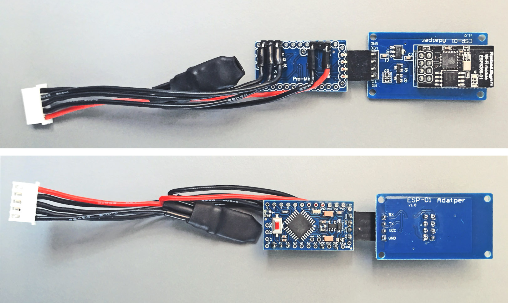
I would like to advise you to not solder a fixed connection between the Arduino and ESP-01. Using male and female pin headers for the connection (see figure above) will enable you to easily upload updates the Arduino at a later stage.

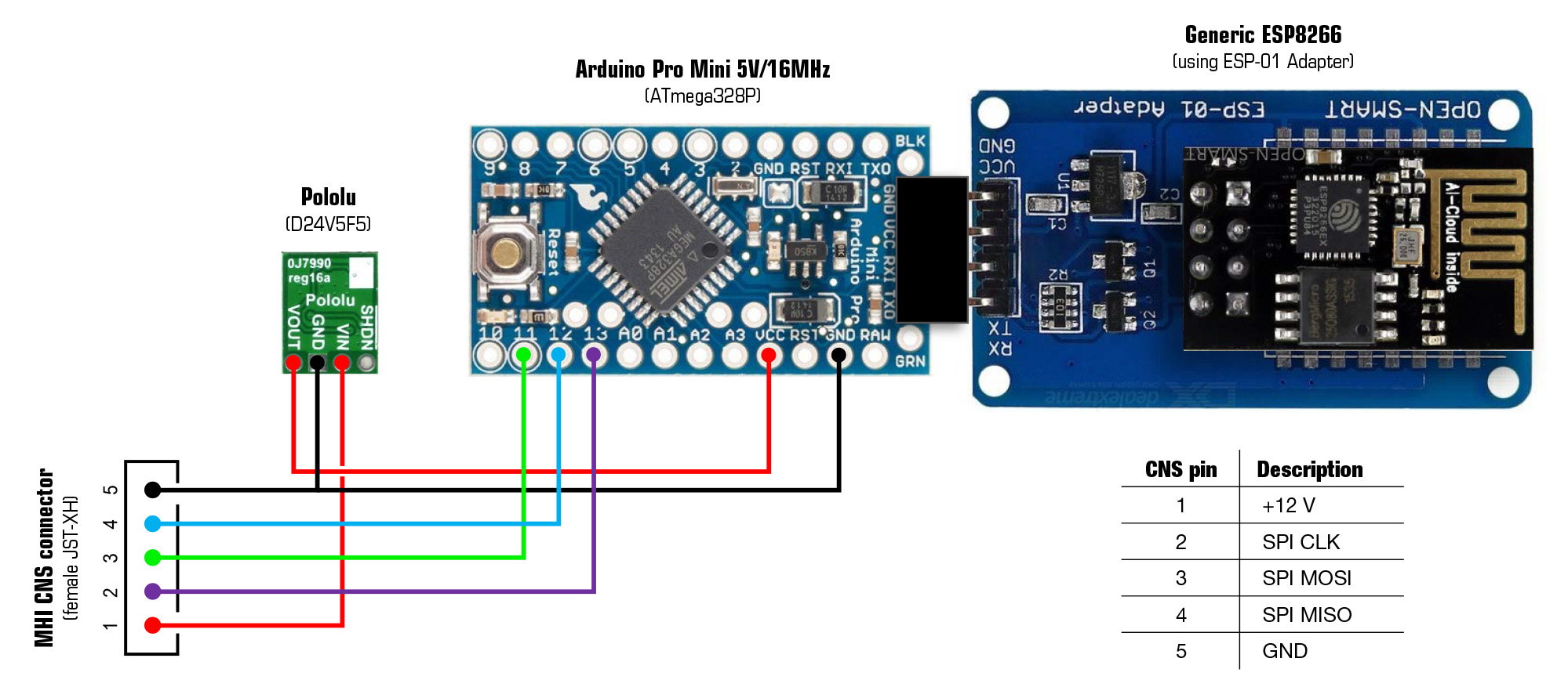
The CNS socket on the MHI indoor unit's PCB accepts a JST-XH 5-pin female connector. It can be bought pre-wired as a 4S LiPo balance cable. In addition, I use a prefab male-to-female version of this cable as an extension cord.

JST-XH pin layout (looking at the male socket on the PCB with the locking protrusions/slots downwards):
Pin 1 (left) = 12V, pin 2 = SPI clock, pin 3 = SPI MOSI, pin 4 = SPI MISO, pin 5 (right) = GND.

Check before connecting with a multitester. GND versus clock should be +5V. If the voltage over outer pins is -12V then connector orientation is wrong. Pins 2 - 5 are 5V and directly compatible with an Arduino Pro Mini 5V/16 MHz version. Note that the 3.3V/8MHz version is NOT directly compatible and logic level conversion is necessary. The 8 MHz is possibly to slow to keep up with SPI communication and data processing, although I didn't test this.

The Arduino Pro Mini is 12V tolerant according to its specs, but using the 12V (pin 1) of the MHI unit did not work in my setup. I use a Pololu D24V5F5 step-down voltage regulator to power both the Pro Mini and the ESP8266.

Oh, and while you're at it, take out the two LEDs on the Arduino. They are ridiculously bright. Really, the light will pass through the plastic casing and will light up your aircon like it's Christmas all year. It's better to use a soldering iron to do this (find good instructions on YouTube). Do not start cutting the LEDs traces as you will likely damage traces underneath.

After soldering and uploading the firmware, I wrapped the entire contraption in shrink wrap to fix all the (re)movable parts and protect against causing possible short-circuits while installed in the aircon.

Contraption

Parts

Installation

Dependencies

The following additional libraries are necessary and should be added to the Arduino IDE before compiling and flashing the sketches:

  • WiFiManager - For managing the WiFi connection and changing MQTT settings
  • PubSubClient - MQTT client
  • EasyTransfer - Takes care of serial communication between the Pro Mini and ESP-01
  • ArduinoJson - JSON library for reading and storing WiFiManager settings in flash memory

Installing the sketches

Two sketches are provided:

  • Arduino Pro Mini
    Upload MHI-SPI2ESP.ino using the Arduino IDE and an FTDI USB-serial adapter.
    In the Arduino IDE, select Arduino Pro or Pro mini under Tools > Board and select ATmega328P (5V, 16 MHz) under Tools > Processor.

  • ESP-01 ESP8266 WiFi module
    Optional: Change the name (SSID) and password of the access point that is started by the ESP-01 for configuration on first boot (lines 21-22 of MHI-ESP2MQTT.ino). This is not the name of your home WiFi network (SSID)! I use the name of the room the air conditioner is in.
    Upload MHI-ESP2MQTT.ino using the Arduino IDE and an ESP-01 ESP8266 USB-UART Adapter.
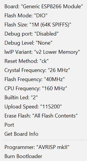
    In the Arduino IDE, select Generic ESP8266 Module under Tools > Board. I have used the following settings (running at 160 MHz is probably not necessary):

Arduino IDE settings

Once the sketch is flashed for the first time, future updates to the ESP-01 can also be uploaded OTA. Name and password are equal to those set for the configuration access point (Default: MHI Roomname with password mitsubishi). The Arduino Pro Mini cannot be updated OTA.

Connecting and configuring the system

  • Disconnect the mains
  • Connect the circuit to the air conditioner's CNS connector*
  • Reconnect the mains
  • Using a tablet or smart phone, connect to the ESP-01's SSID (default: MHI Roomname, or as configured in line 21 of MHI-ESP2MQTT.ino)
  • Default password is mitsubishi, or as configured in line 22 of MHI-ESP2MQTT.ino
  • The configuration portal should display automatically within a few seconds. If not, open a browser and enter 192.168.4.1.
  • Select Configure WiFi
  • Select the home network on which the MQTT broker is running
  • Enter the WiFi password
  • Enter the IP address and port number of the MQTT broker
  • Enter the MQTT username and password (leave empty if not used)
  • Optional: Change the WiFi Timeout (max. 99 minutes; default: 5 minutes). Don't set it too high or it will take a long time before it will reconnect after the network has been down.
  • Set the name of the room that the aircon is in (all available MQTT topics will have the prefix Roomname/Aircon/...). You can add deeper topic levels in the Roomname field (e.g. Bedroom/John).
  • Optional: Change the name of the unit (default: Aircon)
  • Optional: Change topic names for setpoint, state, vanes, fan speed, debug and service
  • Topic names that start with status by default, will be updated with the current aircon settings every ~6 seconds, or directly after a new setting is acknowledged by the aircon
  • Select Save

The system will connect to the selected WiFi network and the MQTT broker. You can quickly check if everything works by using the command line to temporarily subscribe to the relevant topics: Roomname/Aircon/#. If all is well, a successful connection will be notified on the debug topic. Within ~10 seconds after connection, the aircon's current settings will be sent to the status topics. From now on, sending payloads to the topics (see table below under Wireless operation using MQTT) should cause the aircon to respond within max. 2 seconds. All successful commands will be acknowledged by the aircon on the respective status topic.

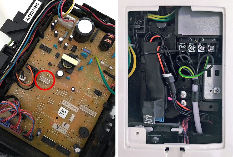
* Google for a service manual of your aircon model for instructions on how to get access to the CNS connector. The image below is of an SRK50ZS-S where I extended the CNS connector from the more difficult-to-reach side panel to the front mains connection box for easy access. Please switch off the mains before doing this and take care that the module is properly isolated (e.g. shrink wrap) and fixed with a cable tie so it can't touch the high-voltage terminals.

Installed

Wireless operation using MQTT

The table below shows the topics and respective value range that can be used to operate the aircon:

MHI2MQTT Topics & Values

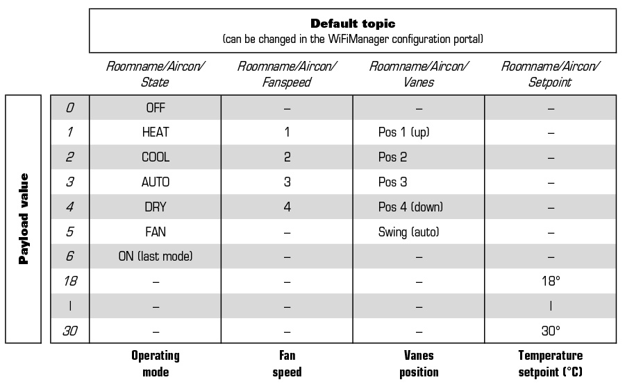
The default topic statusRoomtemp will be updated with the ambient temperature (in degrees Celsius) every ~6 seconds.
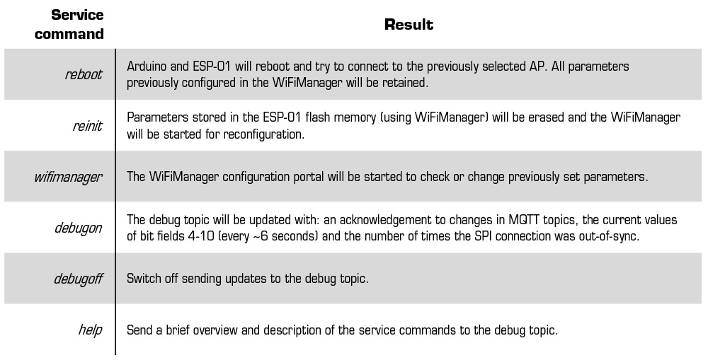
Various service commands can be send to the service topic and the system will respond as follows:

MHI2MQTT Service commands

Behavior when the WiFi network or MQTT broker is down

  • When the MQTT broker becomes inaccessible, three reconnection attempts will be made by the ESP-01 with ~5 seconds in between. The system will restart if this fails and will first try to reconnect to the access point and then to the MQTT server. This behavior was chosen because if the network client running the MQTT broker disconnects from the access point, the ESP-01 will still be unable to connect to the broker after the client has reconnected. A complete restart of the ESP-01 and reconnection to the access point solves this.
  • When the WiFi connection between the ESP-01 and the access point is lost, the system will restart after a while and WiFiManager will try to connect to the previously configured access point. If this still fails, WiFiManager will start in access point mode (SSID default: MHI Roomname) awaiting reconfiguration by connecting to it. After the timeout previously set in the configuration portal has passed (default: 5 minutes), the ESP-01 will restart again and try to reconnect to the previously configured access point. These events will loop endlessly, giving some time to change the configuration when the router SSID, password or MQTT broker host has changed. The ESP-01 should always reconnect after a general power outage, but this might take 5 minutes or more.

Notes

Details about the communication protocol

  • Low-level SPI protocol exchanging frames of 20 bytes/bit fields using LSB first, 8 bits/transfer, clock is high when inactive (CPOL=1), data is valid on clock trailing edge (CPHA=1). Timing details of 20-byte SPI frames: 1 byte ~0.5 msec; 20-byte SPIframe ~10 msec; pause between two frames ~30 msec. Time between the start of 2 consecutive frames is ~40 msec (~25 Hz).
  • High-level SPI protocol where master (MHI) and slave (Arduino) exchange a repetitive pattern of special bit settings in bit fields 10, 13-16 and 18. In contrast to the low-level SPI protocol, the SPI slave now functions as a 'master' and generates what appears to be its own low frequency clock (~0.5 Hz) by toggling bit 3 of bit field 18 every 24 SPI frames. All bidirectional changes in values are synchronous to this 'clock', with few exceptions such as the room temperature in bit field 7. To successfully connect, a sequence of 3 repeating SPI frame variants should be send to the MHI. If correct, the MHI will respond by sending its own frame variations to acknowledge a valid SPI connection (?). Possibly, the frame variations send back by the MHI identify the unit type and can be used by the controller to make unit-specific functions available. Each frame variation is send 24 times with bit 3 of bit field 18 set to 1, and subsequently 24 times with bit 3 cleared. The total duration of a complete frame cycle (3 frame variations x 48 times each) is ~6 sec, then the sequence is started all over. All changes in settings should be send synchronously to the byte 18 'clock', starting at the beginning of the first SPI frame that has bit 3 of bit field 18 set to 1, and lasting the full duration of a clock cycle (= 48 SPI frames). In order to change a setting on the MHI, the correct bit fields should be set/cleared AND a function-specific 'write' bit should be set to 1 for a full 48-frame cycle in order to have the MHI accept and apply the new setting. For all subsequent frames, only the 'write' bit should be set back to 0, while the rest of the newly set bits should be unaltered. If the change is accepted, the MHI will start sending back the newly accepted settings starting from the next full 48-frame cycle.

Notes on handling SPI communication in the code

The Arduino Mini Pro had problems staying in sync with the aircon's SPI data during the early test phase. To solve this, a state machine type of approach was chosen to prevent the SPI interrupt routine from being obstructed (by e.g. UART serial communication with the ESP-01) until a full 20-byte is received (state 0). Then, two states are possible: one to update frames, calculate checksums and send values obtained from the aircon to the ESP-01 (state 1); and one where the serial connection is checked for data arriving from the ESP-01 (state 2). When debugging is enabled using the service command debugon, the debug topic will provide a cumulative count of the number of SPI synchronisation errors (until a reboot/reset). I never ran into sync issues anymore since I started using the state machine approach, so this debugging feature is obsolete unless you want to test the sketch on other Arduino boards.

Acknowledgments

This work would not have been possible in the current form without the ingenious work of others: WiFiManager by Tzapu, PubSubClient by Nick O'Leary, EasyTransfer by Bill Porter and ArduinoJson by Benoît Blanchon. In addition to using these libraries, parts of the code were obtained from the example sketches.

License

This project is licensed under the terms of the MIT license.

mhi2mqtt's People

Contributors

rjdekker avatar

Stargazers

 avatar  avatar  avatar  avatar  avatar  avatar  avatar  avatar  avatar  avatar  avatar  avatar  avatar  avatar  avatar  avatar  avatar  avatar  avatar  avatar  avatar  avatar  avatar  avatar  avatar  avatar  avatar  avatar  avatar  avatar  avatar  avatar  avatar  avatar  avatar  avatar  avatar  avatar  avatar  avatar  avatar  avatar  avatar  avatar  avatar  avatar  avatar  avatar  avatar  avatar  avatar  avatar  avatar  avatar  avatar  avatar  avatar  avatar  avatar  avatar  avatar  avatar  avatar  avatar  avatar  avatar  avatar  avatar  avatar  avatar  avatar  avatar  avatar  avatar  avatar  avatar  avatar  avatar  avatar  avatar  avatar  avatar  avatar  avatar  avatar  avatar  avatar  avatar  avatar  avatar  avatar  avatar  avatar  avatar  avatar  avatar  avatar  avatar  avatar  avatar

Watchers

 avatar  avatar  avatar  avatar  avatar  avatar  avatar  avatar  avatar  avatar  avatar  avatar  avatar  avatar  avatar  avatar  avatar  avatar  avatar  avatar  avatar  avatar  avatar  avatar

mhi2mqtt's Issues

Question about OTA

Hi,

first, thank you for the great work - I am using your design since 6 Months, without any big issues (controlling 4 MHI SRK via mqtt from fhem)

I just recently noticed that all 4 modules open an hotspot allthough configured and connected.
Is this used for OTA? Or is OTA done via the usual connected WLAN and it is a bug that the hotspot mode comes up in normal "production" mode?

Thank you for your input, and best regards
Markus

Power/Econo mode?

Good Morning/Afternoon/Evening..
I'm wanting to use something exactly like this to control my 2 MHI aircons.
the larger (model escapes me right now) offers an eco mode which runs in a low power mode. One of the reasons i want to be able to control them is in the event my mains grid fails and i run on battery. - to maximise battery life i first want to reduce to eco mode and then off. Has anyone any idea what bitfields eco mode might use?
(the remote control has a combined power/eco mode - 1 push give power mode, 2 gives eco mode).
I guess i will have to monitor the unit for state change when i manually enter eco mode.

No Hotspot / no Connection

Hi,

first, many many thanks for this project. Works fine for the first time, but i wanted to change the names. So i restart in hotspot mode an change the names. After reboot i had no more connection to my wifi and no hotspot is there. Any idea? What can i do?
I think i will try to flash the ESP Modul again to see if it works

MQTT not responding

When I subscribe to debug channel the ESP send me, I suppose, the help message, but I don't receive anything on all status channels and when I send something to set values nothing happens. Even the service channel seems dead. I've tried with different brokers but nothing. Any idea?

ESP not active when connected to aircon

Hi,

I'm facing issues with the interface when i connect it to the aircon.

When putting 12V by an external power supply the interface is running (Arduino & ESP all lamps on, connected to wifi)

But when i connect the interface to the aircon just the Arduino is active - the ESP is not showing any LED or connects to the wifi.

I've double checked the wires and CLK Port - everything is fine.

Does anybody has an idea how i can get it working?

Best Regards

Manuel

Use ESP8266 only?

I'm getting some questions if it is possible to only use an ESP8266-based board without the Arduino.

The thing is that this is what I was aiming for when starting this project. Unfortunately, I could not get SPI communication working with the MHI. The reason is technical and mostly beyond my skills. Running an ESP8266 as a SPI slave (MHI is master) is very poorly documented and some code that I found was impossible for me to get working for this particular scenario.

Some of the things that I ran into:

  • The MHI does not use a slave select line and the ESP8266 SPI library does
  • The MHI's clock is high when idle. The ESP8266 appears to only work with clock low when idle.
  • Cryptic documentation on the ESP's SPI hardware

I still think it's possible but it would cost me too much time to figure out.

In contrast, I had the Arduino working as a SPI slave in no time and the programmatic implementation was delightfully simple compared to the ESP8266.

If anyone knows how to do this, I will be happy to provide you with more detailed information on the SPI protocol.

Cheers, Rob

Only get subscription response from Roomname/Aircon/#

Thankyou for sharing this awesome writeup. I am using a RPI with openhab2 and mosquitto and can subscribe to Roomname/Aircon/# (giving me the response = "MHI2MQTT connected to MQTT broker at 192.168.1.148:1883" however any other subscriptions i enter return nothing eg. Roomname/Aircon/State
Roomname/Aircon/Fanspeed etc

this is the first time i have used mqtt so am i doing something wrong here or do i need to reflash the arduino pro ? appreciate any help with this.

The only thing you may want to add on your readme for future users is that they should not get the latest version of ArduinoJSON (6) as the INO file requires (5.x) and pops up with errors in the Arduino IDE for the latest version of this library. The only other thing was that on the ESP8266 webpage the maximum character length for the host name is (16 characters) i was trying to debug my code with an online hostname (m16.cloudmqtt.com) but would not fit in the field. That said i could never create the awesomeness that you have here!!

Random generated MQTT devices with changing chars

Hi,

I'm running into some issues with the module in my iobroker mqtt instance. After starting up everything is fine - the devices is recognized by the mqtt server and all items are created. Perfect!

But when i'm using the adapter it seems that there is a wrong feedback from the adapter hat creates devices with special chars. Attached a screenshot.

First i was thinking about german special chars (Umlaute) but i only use regular chars. Also debug-mode is of. I think it's issue in the debug feedback. Is there an option to completly deactivate feedback from this part?

Best Regards

Manuel
Bildschirmfoto 2020-04-27 um 08 32 15

compile error?

C:\Users\steph\Downloads\rjdekker-MHI2MQTT-e737f6e\src\MHI-SPI2ESP\MHI-SPI2ESP.ino: In function 'void SPI_sync()':

C:\Users\steph\Downloads\rjdekker-MHI2MQTT-e737f6e\src\MHI-SPI2ESP\MHI-SPI2ESP.ino:152:49: warning: invalid conversion from 'volatile void*' to 'void*' [-fpermissive]

memcpy(&tx_SPIframe[9], &frameVariant[0][0], 9); //Copy (part of) the next frame to the current frame for sending on the upcoming bitfield 18 clock cycle

                                             ^

In file included from C:\Users\steph\Downloads\arduino-1.8.5-windows\arduino-1.8.5\hardware\arduino\avr\cores\arduino/Arduino.h:25:0,

             from C:\Users\steph\AppData\Local\Temp\arduino_build_189773\sketch\MHI-SPI2ESP.ino.cpp:1:

c:\users\steph\downloads\arduino-1.8.5-windows\arduino-1.8.5\hardware\tools\avr\avr\include\string.h:191:14: note: initializing argument 1 of 'void* memcpy(void*, const void*, size_t)'

extern void *memcpy(void *, const void *, size_t);

          ^

C:\Users\steph\Downloads\rjdekker-MHI2MQTT-e737f6e\src\MHI-SPI2ESP\MHI-SPI2ESP.ino: In function 'void loop()':

C:\Users\steph\Downloads\rjdekker-MHI2MQTT-e737f6e\src\MHI-SPI2ESP\MHI-SPI2ESP.ino:275:67: warning: invalid conversion from 'volatile void*' to 'const void*' [-fpermissive]

                   memcpy(&toESP.currentMHI, &rx_SPIframe[3], 7);                                               //Copy bitfields 4-10 from the most recent MHI SPI frame to new array for sending to ESP

                                                               ^

In file included from C:\Users\steph\Downloads\arduino-1.8.5-windows\arduino-1.8.5\hardware\arduino\avr\cores\arduino/Arduino.h:25:0,

             from C:\Users\steph\AppData\Local\Temp\arduino_build_189773\sketch\MHI-SPI2ESP.ino.cpp:1:

c:\users\steph\downloads\arduino-1.8.5-windows\arduino-1.8.5\hardware\tools\avr\avr\include\string.h:191:14: note: initializing argument 2 of 'void* memcpy(void*, const void*, size_t)'

extern void *memcpy(void *, const void *, size_t);

          ^

C:\Users\steph\Downloads\rjdekker-MHI2MQTT-e737f6e\src\MHI-SPI2ESP\MHI-SPI2ESP.ino:308:62: warning: invalid conversion from 'volatile void*' to 'const void*' [-fpermissive]

               memcpy(&rx_bitfield4_10, &rx_SPIframe[3], 7);                                                    //Get bitfields 4-10 from the last MHI SPI frame to use for the upcoming tx_SPIframe update

                                                          ^

In file included from C:\Users\steph\Downloads\arduino-1.8.5-windows\arduino-1.8.5\hardware\arduino\avr\cores\arduino/Arduino.h:25:0,

             from C:\Users\steph\AppData\Local\Temp\arduino_build_189773\sketch\MHI-SPI2ESP.ino.cpp:1:

c:\users\steph\downloads\arduino-1.8.5-windows\arduino-1.8.5\hardware\tools\avr\avr\include\string.h:191:14: note: initializing argument 2 of 'void* memcpy(void*, const void*, size_t)'

extern void *memcpy(void *, const void *, size_t);

          ^

C:\Users\steph\Downloads\rjdekker-MHI2MQTT-e737f6e\src\MHI-SPI2ESP\MHI-SPI2ESP.ino:330:73: warning: invalid conversion from 'volatile void*' to 'void*' [-fpermissive]

           memcpy(&tx_SPIframe[9], &frameVariant[variantnumber][0], 9);                                         //Copy (part of) the next frame to the current frame for sending on the upcoming bitfield 18 clock cycle

                                                                     ^

In file included from C:\Users\steph\Downloads\arduino-1.8.5-windows\arduino-1.8.5\hardware\arduino\avr\cores\arduino/Arduino.h:25:0,

             from C:\Users\steph\AppData\Local\Temp\arduino_build_189773\sketch\MHI-SPI2ESP.ino.cpp:1:

c:\users\steph\downloads\arduino-1.8.5-windows\arduino-1.8.5\hardware\tools\avr\avr\include\string.h:191:14: note: initializing argument 1 of 'void* memcpy(void*, const void*, size_t)'

extern void *memcpy(void *, const void *, size_t);

          ^

get/send values to the ac

Hello,
I connected the arduino to my AC (SRK 35 ZS), the light on the esp is on.
It send a connection-message to my broker, every 6 minutes. I visulize it with mqtt.fx
I send help to the device and it sends {"metrics":[],"seq":0} back, if i change the "payload decoder".
How can i send some commands to my ac, can you make me an example ?

Only the debug message comes back, nothing else. is that normal ?
I subscribe it all (#)

Im a beginner in this case.

Room temperature formula

Hi,
Thanks for you excellent work.
I'm trying to make it work on ESP8266 directly.
But in my case, the room temperature seems to be not very accurate.
Do you remember why the formula was set to
//Calculate current room temperature in degrees Celsius from bitfield 7 using:
// (BF7 - 61) / 4 (note: Calibration of temperature needs to be checked further)
Is it estimated or is there any "reason" for this formula, especially the "- 61" ?
Or does it mean my aircon is not correctly calibrated ?

Best regards.

srk71zma-s working

Confirming that MHIMQTT works with MHI model srk71zma-s. Was able to control with Home Assistant via MQTT

statusRoomTemp from Hass?

Hi Rob,

Love the project and many thanks for putting in the effort to develop and document!

I realise that you no longer have a system to test on and improve this, but I was wondering if it's possible to write values to statusRoomtemp using your code? IE Zigbee temperature values from various rooms.

The main reason I want to use this is as we have an MHI ducted air conditioning system with zones, but only one temperature sensor so the system can cool individual rooms but only sees the central thermostat temperature. Would be good to know if this is possible before I dive into Arduino and buy the components! I'm new to Arduino but have been using RPi for some time.

Cheers,
CanuckianOz

Problem WiFi Setup

I am an old codger from Australia. I am familiar with Arduino, less so with ESP8266. I make the odd Eagle PCB.

I have a few Arduino Mini's, although they don't look identical to your Pro Mini. I also use a MacOSX Big Sur for development.
I have a couple of Adafrruit Huzzah Feather boards. I am interested in the project primarily because I have a large MHI AirCon which is driving me mad, and it does seem to have a lot in common with the environment described.

The documentation provided is terrific, and I have made a lot of progress, but have needed to change things a bit to suit the bits I have.

Firstly Software: The ESP JSON 6 code needed changing to compile - basically to use JsonDocument class. The changes seem to be a bit simpler than the original, due to Json improvements. I also needed to put a Silabs Driver on the Mac to upload to the Huzzah.

Next Hardware. I had to rework the 2 boards. The Huzzah includes a USB connector, and my Mini is loaded through a FTDI connection. To get access to each board for changing software, and for the connector to the MHI I needed a bit different arrangement. I will send a photo if it might be of general interest. I haven't wired the MHI bit yet, as we are in Covid lockdown.

Anyway, on to the problem. Power to the Huzzah and the Mini is via the USB connector on the Huzzah. Mini LED ON.
I search for a Network, and find one which is obviously the ESP board. But its SSID is ESP_C109E7 and unpassworded.
I don't know how to relate it to my home Wifi SSID/PSWD. I also changed the code temporarily to grab this network.

I do get a nice Wifi Manager screen Config Info Update etc etc, but am unsure on what I should be setting where.
When I upload code into the Huzzah via the SiLabs driver, I don't seem to need any Burnloader activity from the Arduino IDE.

Any comments welcome. Sorry this is a bit preliminary.

Peter Hanlon

Upload error flashing

Hi,
i try to flash the arduino pro mini with your sketch.

If I upload the sketch a mistake comes up.

`Arduino: 1.8.10 (Windows 10), Board: "Arduino Pro or Pro Mini, ATmega328P (5V, 16 MHz)"

Der Sketch verwendet 4158 Bytes (13%) des Programmspeicherplatzes. Das Maximum sind 30720 Bytes.
Globale Variablen verwenden 373 Bytes (18%) des dynamischen Speichers, 1675 Bytes für lokale Variablen verbleiben. Das Maximum sind 2048 Bytes.
avrdude: stk500_recv(): programmer is not responding
avrdude: stk500_getsync() attempt 1 of 10: not in sync: resp=0x77
avrdude: stk500_recv(): programmer is not responding
avrdude: stk500_getsync() attempt 2 of 10: not in sync: resp=0x77
avrdude: stk500_recv(): programmer is not responding
avrdude: stk500_getsync() attempt 3 of 10: not in sync: resp=0x77
avrdude: stk500_recv(): programmer is not responding
avrdude: stk500_getsync() attempt 4 of 10: not in sync: resp=0x77
avrdude: stk500_recv(): programmer is not responding
avrdude: stk500_getsync() attempt 5 of 10: not in sync: resp=0x77
avrdude: stk500_recv(): programmer is not responding
avrdude: stk500_getsync() attempt 6 of 10: not in sync: resp=0x77
avrdude: stk500_recv(): programmer is not responding
avrdude: stk500_getsync() attempt 7 of 10: not in sync: resp=0x77
avrdude: stk500_recv(): programmer is not responding
avrdude: stk500_getsync() attempt 8 of 10: not in sync: resp=0x77
avrdude: stk500_recv(): programmer is not responding
avrdude: stk500_getsync() attempt 9 of 10: not in sync: resp=0x77
avrdude: stk500_recv(): programmer is not responding
avrdude: stk500_getsync() attempt 10 of 10: not in sync: resp=0x77
Problem beim Hochladen auf das Board. Hilfestellung dazu unter http://www.arduino.cc/en/Guide/Troubleshooting#upload.

Dieser Bericht wäre detaillierter, wenn die Option
"Ausführliche Ausgabe während der Kompilierung"
in Datei -> Voreinstellungen aktiviert wäre.
`

Can anyone explain what I'm doing wrong?

Compilation error: DynamicJsonBuffer is a class from ArduinoJson 5

.../MHI-ESP2MQTT.ino:132:11: error: DynamicJsonBuffer is a class from ArduinoJson 5. Please see https://arduinojson.org/v7/upgrade-from-v5/ to learn how to upgrade to ArduinoJson 7
  132 |               DynamicJsonBuffer jsonBuffer;
      |           ^   ~~~~~~~~~~~~~~~~~~~~~~~~~~~~~                                                                                                                  
.../MHI-ESP2MQTT.ino:308:11: error: DynamicJsonBuffer is a class from ArduinoJson 5. Please see https://arduinojson.org/v7/upgrade-from-v5/ to learn how to upgrade to ArduinoJson 7
  308 |       DynamicJsonBuffer jsonBuffer;
      |           ^~~~~~~~~~~~~~~~~~~~~~~~~                                                                                                                          

exit status 1

Compilation error: DynamicJsonBuffer is a class from ArduinoJson 5. Please see https://arduinojson.org/v7/upgrade-from-v5/ to learn how to upgrade to ArduinoJson 7

DynamicJSONBuffer not longer supported in Arduino 6

Hi,

when i try to verify / compile the MHI-ESP2MQTT there is shown an error:

MHI-ESP2MQTT:132:11: error: DynamicJsonBuffer is a class from ArduinoJson 5. Please see arduinojson.org/upgrade to learn how to upgrade your program to ArduinoJson version 6 DynamicJsonBuffer jsonBuffer; ^ MHI-ESP2MQTT:308:11: error: DynamicJsonBuffer is a class from ArduinoJson 5. Please see arduinojson.org/upgrade to learn how to upgrade your program to ArduinoJson version 6 DynamicJsonBuffer jsonBuffer; ^ exit status 1 DynamicJsonBuffer is a class from ArduinoJson 5. Please see arduinojson.org/upgrade to learn how to upgrade your program to ArduinoJson version 6

How must i change the both lines where it is used? I tried "DynamicJsonDocument jsonBuffer(1024);" but then it's running into next errors. Or is there a way to tell the Arduino IDE to use v5 instead of v6?

Best Regards and thanks for that great work

Manuel

Recommend Projects

  • React photo React

    A declarative, efficient, and flexible JavaScript library for building user interfaces.

  • Vue.js photo Vue.js

    🖖 Vue.js is a progressive, incrementally-adoptable JavaScript framework for building UI on the web.

  • Typescript photo Typescript

    TypeScript is a superset of JavaScript that compiles to clean JavaScript output.

  • TensorFlow photo TensorFlow

    An Open Source Machine Learning Framework for Everyone

  • Django photo Django

    The Web framework for perfectionists with deadlines.

  • D3 photo D3

    Bring data to life with SVG, Canvas and HTML. 📊📈🎉

Recommend Topics

  • javascript

    JavaScript (JS) is a lightweight interpreted programming language with first-class functions.

  • web

    Some thing interesting about web. New door for the world.

  • server

    A server is a program made to process requests and deliver data to clients.

  • Machine learning

    Machine learning is a way of modeling and interpreting data that allows a piece of software to respond intelligently.

  • Game

    Some thing interesting about game, make everyone happy.

Recommend Org

  • Facebook photo Facebook

    We are working to build community through open source technology. NB: members must have two-factor auth.

  • Microsoft photo Microsoft

    Open source projects and samples from Microsoft.

  • Google photo Google

    Google ❤️ Open Source for everyone.

  • D3 photo D3

    Data-Driven Documents codes.