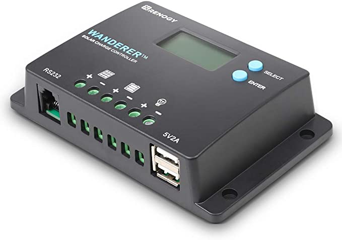
This lets you read data from Renogy charge controllers via their RS232 port using an ESP32 or Arduino.
The inspiration came when I needed to power a pump at a remote pond whenever there was sufficient power from a solar panel, and I was surprised to learn that the load switch on the Renogy controllers can't do that natively. The load switch is only designed to control lights at night. Silly. This lets me use the load switch to power whatever I want, but see the "Notes on the Load Switch" below for some notes on its limitations. And of course it lets me do whatever else I want with the data from the Renogy charge controller including using a relay, and gives me a dirt cheap way to read the battery voltage, panel voltage and load wattage from an ESP32 or Arduino.
So far I've only tested this with Renogy Wanderer 30A (CTRL-WND30-LI) and Wanderer 10A charge controllers, please post to the Issues section if you test on more and I'll add it to the list below. It should work with any Renogy charge controller that has an RS232 port, which I think is all of them since they want to sell their bluetooth module that works with the RS232 port.
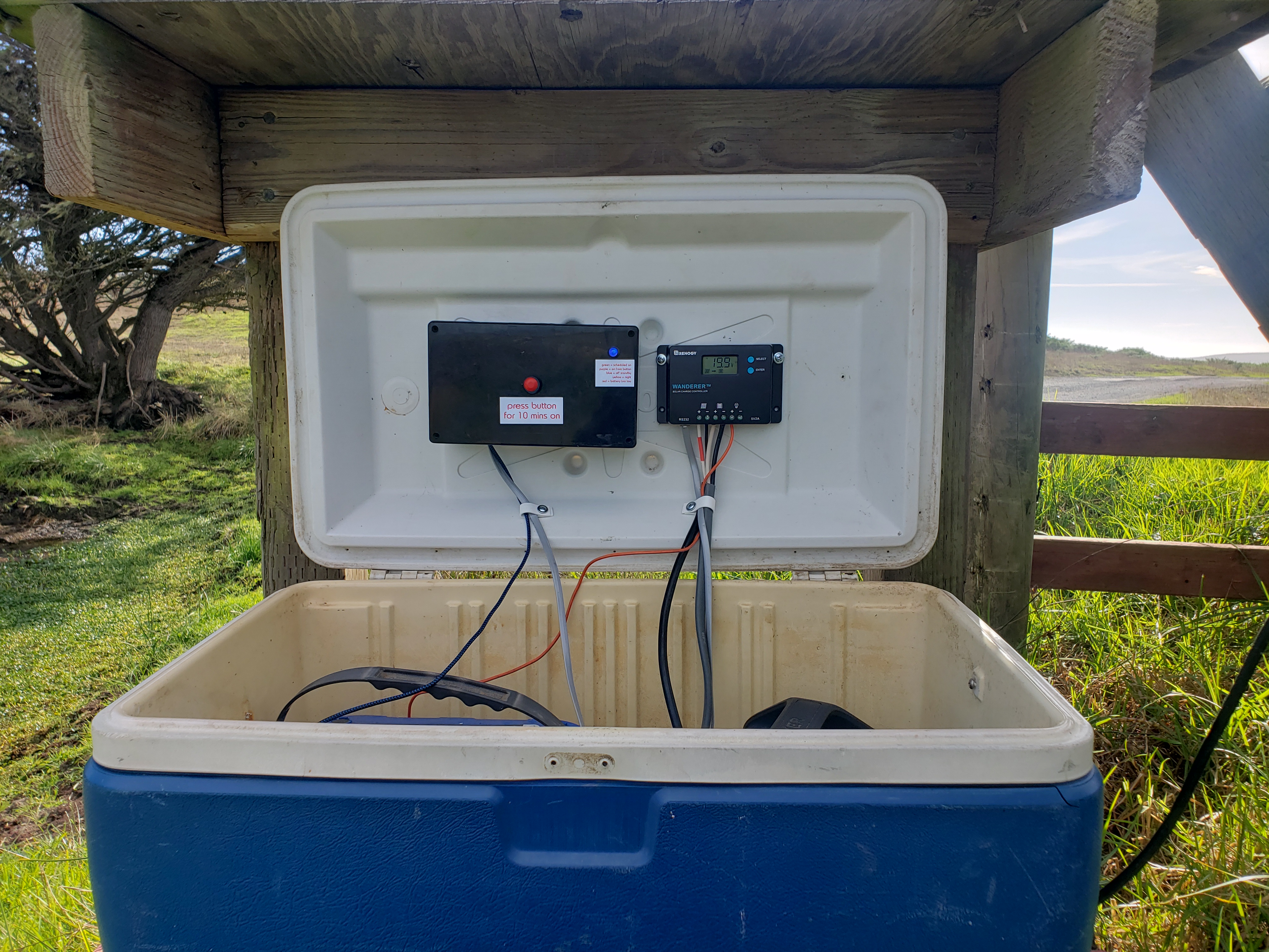
Here's a pic of my installation:
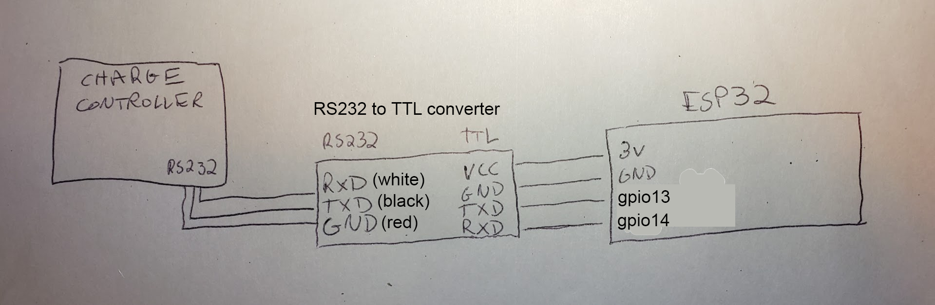
Here's an overall wiring diagram:
You'll need make a cable to connect the controller to your ESP32 or Arduino. Start with an RJ12 cable, which is an old phone cable with 6 wires. Make sure it doesn't have only 4 wires, which is an RJ11 cable.
Here's the RJ12 jack on my cable, note how there's 6 wires (white, black, red, green, yellow, blue):
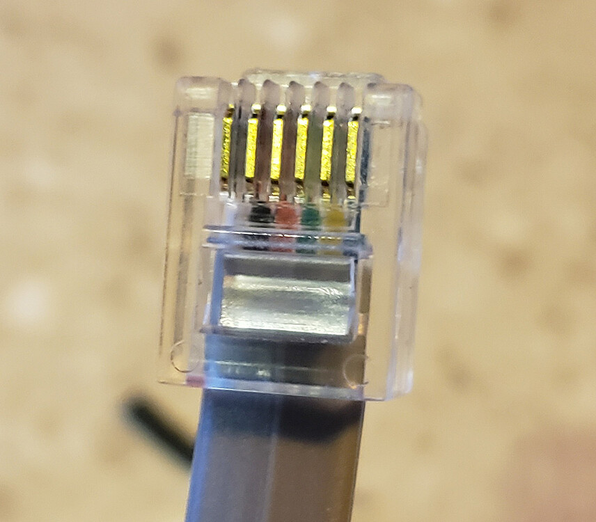
I don't know how standard the wire colors are but those are the colors on mine. You need the first 3 wires from the left, which on mine are the white, black and red wire.
You'll also need a TTL to RS232 level adjuster. I used this one but there are lots of other options (google "max3232"):
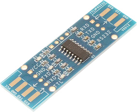
If the listing goes away, it's the "NOYITO TTL to RS232 Module TTL RS232 Mutual Conversion Module", costs $7. See the wiring diagram above for instructions on connecting to it.
After connecting the cable and flashing your ESP or Arduino you should be seeing data from your charge controller in Serial Monitor:
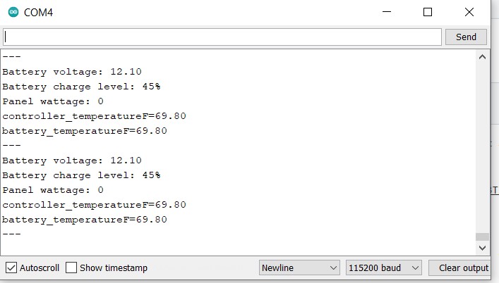
Feel free to post to Issues if not.
There's a struct that holds all the data from the charge controller. A look at the struct shows what data that is:
struct Controller_data {

  uint8_t battery_soc;               // percent
  float battery_voltage;             // volts
  float battery_charging_amps;       // amps
  uint8_t battery_temperature;       // celcius
  uint8_t controller_temperature;    // celcius
  float load_voltage;                // volts
  float load_amps;                   // amps
  uint8_t load_watts;                // watts
  float solar_panel_voltage;         // volts
  float solar_panel_amps;            // amps
  uint8_t solar_panel_watts;         // watts
  float min_battery_voltage_today;   // volts
  float max_battery_voltage_today;   // volts
  float max_charging_amps_today;     // amps
  float max_discharging_amps_today;  // amps
  uint8_t max_charge_watts_today;    // watts
  uint8_t max_discharge_watts_today; // watts
  uint8_t charge_amphours_today;     // amp hours
  uint8_t discharge_amphours_today;  // amp hours
  uint8_t charge_watthours_today;    // watt hours
  uint8_t discharge_watthours_today; // watt hours
  uint8_t controller_uptime_days;    // days
  uint8_t total_battery_overcharges; // count
  uint8_t total_battery_fullcharges; // count

  // convenience values
  float battery_temperatureF;        // fahrenheit
  float controller_temperatureF;     // fahrenheit
  float battery_charging_watts;      // watts. necessary? Does it ever differ from solar_panel_watts?
  long last_update_time;             // millis() of last update time
};
Controller_data renogy_data;
For example there's battery_soc (battery state of charge), the battery_voltage, the battery_charging_amps, etc. There's examples in the code of how to access them, but for example you get the battery voltage like this:
Serial.println( renogy_data.battery_voltage );
There's another struct that holds the info about the charge controller (it's voltage rating, amp rating, serial number, etc). I don't think all those are working yet. For example the serial number it reports is different than the one printed on my charge controller, which I think is just because of how my code processes the serial number data, but I don't need that functionality so I haven't fixed that yet.
And note the commented out section in the code that turns the load switch on and off. For example this would turn the load on for 10 seconds:
renogy_control_load(1)
delay(10000);
renogy_control_load(0)
I think the load switch uses a MOSFET, which means anything with an inductive kickback (like a brush motor) might damage the switch or the unit itself. But I've been powering a bilge pump on it, which I think is an inductive load, for months without an issue. I'm willing to risk my cheapie PWM charge controller for that, but be careful what you power from the load switch directly. And of course you can connect a relay to the load switch to control anything else, or just connect a relay directly to your Arduino or ESP32.
Renogy is oddly uncommunicative about the limits of the load switch, and my theory is that that's because it's a bit complicated. My theory is that the capacity is shared between the battery input and the switch output. So for example if the 10 amp charge controller is pulling 8 amps of power from the solar panels, that leaves only 2 amps for the load switch. That would explain both why they don't mention the actual load limit, and why they only let us control the load at night (when the solar panels aren't competing for the capacity). But still, if that's the case, it would be nice for Renogy to mention that. And furthermore having options to control the load switch in the day would allow for someone to either have a larger controller than their panel so daytime power wouldn't be an issue, or to just use a relay connected to the load switch. Furthermore the manual says the controller will shut off the load switch and show an error code if the capacity reaches 105%, so maybe exceeding the load limit by a bit isn't catastrophic.
Anyway you can of course bypass all these issues by just controlling a relay directly from your ESP or Arduino.
For the record here's a screenshot from the Renogy Wanderer 10a manual showing the modes of the load switch:
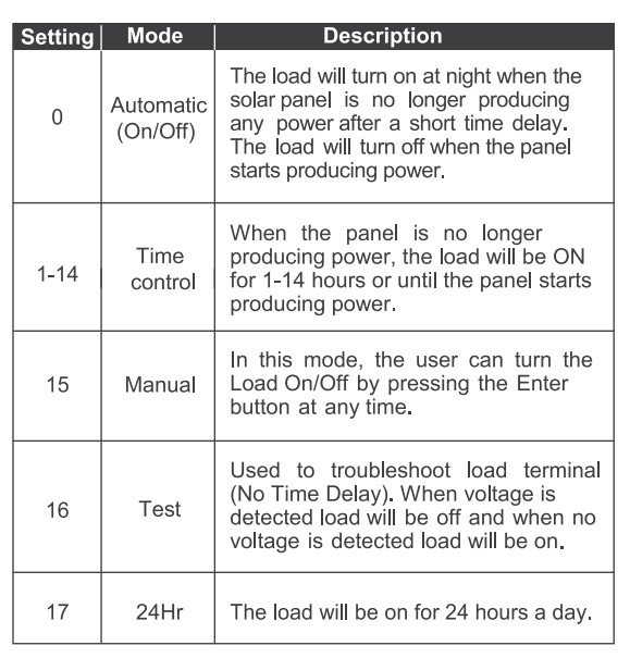
Such an odd limitation to design them only to handle lights. Oh well, nothing an ESP32 or Arduino can't fix.
-
as of now this is untested on an Arduino, I've only used it with ESP32's (both a Rover and a Wroom). It should work fine with an Arduino, the only thing I'm uncertain about is whether you can have two Serial interfaces with all Arduinos (and this script uses one Serial interface for communication with the Renogy controller and one to print status to the console). It should work fine though. If you test with an Arduino please post to this project's Issues section.
-
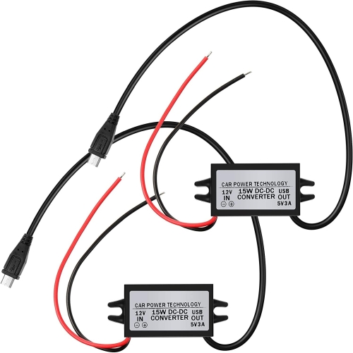
I couldn't power the ESP32 directly from the charge controller, my theory is that it's so low power that the charge controller thinks nothing is connected and shuts off the USB port. Oh well, I used one of these 12v to 5v adaptors:
There's a couple of other projects that get data from the Renogy charge controllers. Oddly I couldn't find anything that uses an ESP32 or Arduino though.
Much thanks to them! They made this much easier.
Those are all for Raspberry Pi's or similar though. For my use case a Raspberry Pi is vastly overkill and has a lot of drawbacks: it needs to be shutdown properly, has a corruptible SD card, uses about 10 times the power of an Arduino or ESP (and an ESP32 can use deep sleep mode, which uses almost no power at all), has a super slow bootup time as opposed to instantly on, has an OS which needs to be kept up to date and is subject to lock ups, etc. ESP32's are in general much more robust in my experience. Once you get it working it just works, I'm betting for decades. That's not to say there aren't times where a Pi or similar makes more sense of course, but a remote solar installation probably isn't one of them.
I also attached Renogy's RS232/modbus manual, it's somewhat occaisonally helpful if you squint at it long enough.
So far it's been tested and confirmed working well on these controllers:
- Wanderer 30A (CTRL-WND30-LI)
- Wanderer 10A
It should work on any Renogy charge controller with an RS232 port. And most if not all of them have that port since Renogy wants to sell their bluetooth module, which uses that port to get its data. This should also be pretty easy to adapt to other charge controllers that make their data available via modbus.
Please post to the Issues section if you test on other Renogy charge controllers, or email me ([email protected]).
-
I don't think it's correctly reading the serial number register, and possibly some of the other registers having to do with the model number. Please let me know if you figure out any fixes. ([email protected] or post to Issues).
-
would be nice to add Bluetooth support for monitoring from a phone, posting to MQTT brokers and pvwatts, etc.


