GithubHelp home page GithubHelp logo

jbuckmccready / cavaliercontours Goto Github PK

View Code? Open in Web Editor NEW
378.0 18.0 78.0 210 KB

2D polyline library for offsetting, combining, etc.

License: MIT License

C++ 95.79% CMake 1.86% C 2.36%
algorithm 2d cad cam computational-geometry geometry spatial-index hilbert-curve

cavaliercontours's Introduction

Summary

NOTE: This C++ library is not being actively developed. Development is continuing in Rust (with a C FFI), the repository is here. This repository will remain available but I do not plan to add new features or fix bugs due to lack of time and motivation! I recommend using the Rust library C API from C++, but if you'd like to help maintain the C++ then pull requests are welcome.

C++14 header only library (with a C API available) for processing 2D polylines containing both straight line and constant radius arc segments. Supports contour/parallel offsetting, boolean operations (OR, AND, NOT, XOR) between closed polylines, and other common functions (winding number, area, path length, distance to point, etc.). For interactive UI and development go to the development project CavalierContoursDev. For quick code examples look in the examples. Live web demo available here (note the page is quite large and may take a minute to download, it's created by building the CavalierContoursDev project to web assembly using Emscripten). For the C API header look here.

Table of Contents

Quick Code Example

#include "cavc/polylineoffset.hpp"

// input polyline
cavc::Polyline<double> input;
// add vertexes as (x, y, bulge)
input.addVertex(0, 25, 1);
input.addVertex(0, 0, 0);
input.addVertex(2, 0, 1);
input.addVertex(10, 0, -0.5);
input.addVertex(8, 9, 0.374794619217547);
input.addVertex(21, 0, 0);
input.addVertex(23, 0, 1);
input.addVertex(32, 0, -0.5);
input.addVertex(28, 0, 0.5);
input.addVertex(39, 21, 0);
input.addVertex(28, 12, 0);
input.isClosed() = true;

// compute the resulting offset polylines, offset = 3
std::vector<cavc::Polyline<double>> results = cavc::parallelOffset(input, 3.0);

NOTE: If the offset results are wrong in some way you may need to adjust the scale of the numbers, e.g. scale the inputs up by 1000 (by multiplying all the X and Y components of the vertexes by 1000), perform the offset (with the offset value also scaled up by 1000), and then scale the output result back down by 1000. This is due the fixed bit representation of floating point numbers and the absolute float comparing and thresholding used by the algorithm.

Polyline Structure

Polylines are defined by a sequence of vertexes and a bool indicating whether the polyline is closed or open. Each vertex has a 2D position (x and y) as well as a bulge value. Bulge is used to define arcs, where bulge = tan(theta/4). theta is the arc sweep angle from the starting vertex position to the next vertex position. If the polyline is closed then the last vertex connects to the first vertex, otherwise it does not (and the last vertex bulge value is unused). See [2] for more details regarding bulge calculations.

Other Programming Languages

CavalierContours is written in C++ and makes available a C API. Here are some wrappers in other languages:

Python (wraps the C API)

Offset Algorithm and Stepwise Example

  1. Generate raw offset segments from the input polyline, pline.
  2. Create the raw offset polyline, pline1, by trimming/joining raw offset segments acquired in step 1.
  3. If the input polyline, pline, has self intersections or is an open polyline then repeat steps 1 and 2 with the offset negated (e.g. if the offset was 0.5 then create raw offset polyline with offset of -0.5), this is known as pline2.
  4. Find all self-intersects of pline1. If step 3 was performed then also find all intersects between pline1 and pline2. If pline is an open polyline then also find intersects between pline1 and circles at the start and end vertex points of pline with radius equal to the offset.
  5. Create a set of open polylines by slicing pline1 at all of the intersect points found in step 4.
  6. Discard all open polyline slices whose minimum distance to pline is less than the offset.
  7. Stitch together the remaining open polyline slices found in step 6, closing the final stitched results if pline is closed.

The algorithm is mostly based on Liu et al. [1] with some differences since the algorithm they describe for GCPP (general closest point pair) clipping fails for certain inputs with large offsets (or at least I am unable to make their algorithm work).

The key clarifications/differences are:

  • When raw offset segments are extended to form a raw offset polyline they are always joined by an arc to form a rounded constant distance from the input polyline.
  • Dual offset clipping is only applied if input polyline is open or has self intersects, it is not required for a closed polyline with no self intersects.
  • If the polyline is open then a circle is formed at each end point with radius equal to the offset, the intersects between those circles and the raw offset polyline are included when forming slices.
  • GCPP (general closest point pair) clipping is never performed and instead slices are formed from intersects, then they are discarded if too close to the original polyline, and finally stitched back together.
  • No special handling is done for adjacent segments that overlap (it is not required given the slice and stitch method).
  • Collapsing arc segments (arcs whose radius is less than the offset value) are converted into a line and specially marked for joining purposes.

Here is example code and visualizations of the algorithm operating on a closed polyline with no self intersects as input.

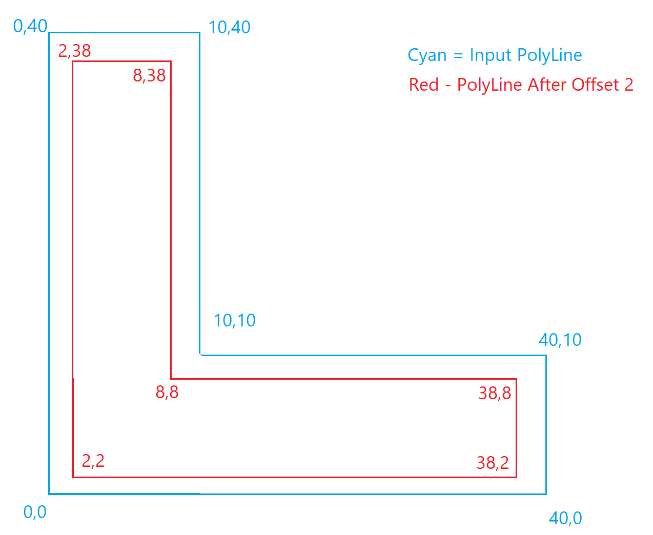
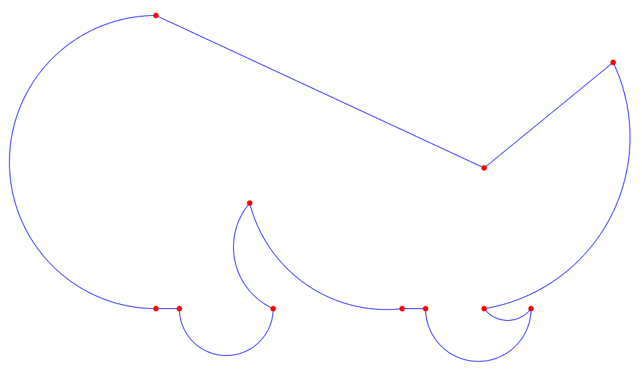
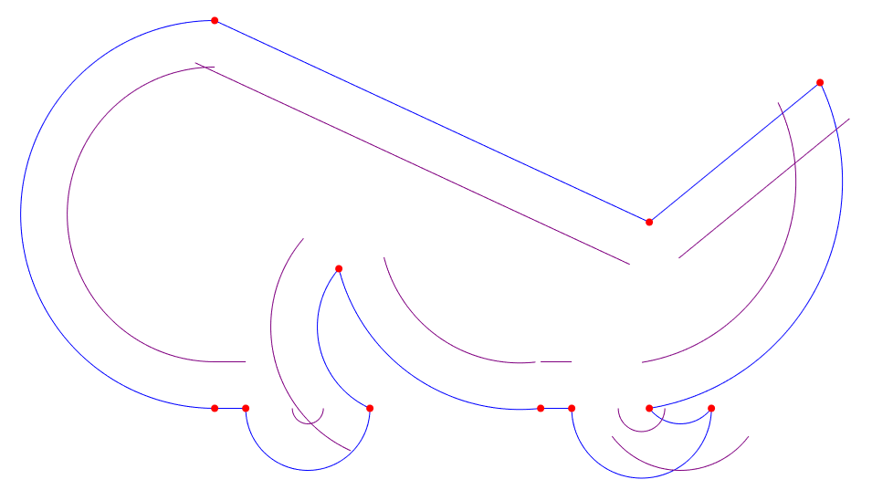
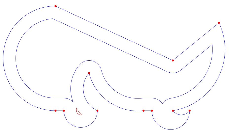
Original input polyline, pline in blue, vertexes in red

Input Polyline

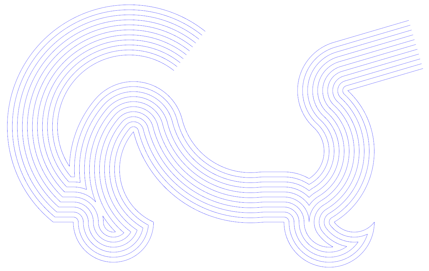
Raw offset segments generated in purple (Step 1)

Raw Offset Segments

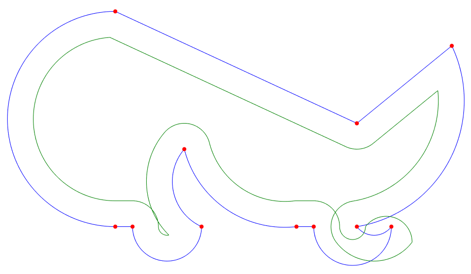
Raw offset polyline created from raw offset segments, pline1 (in green) (Step 2)

Raw Offset Polyline

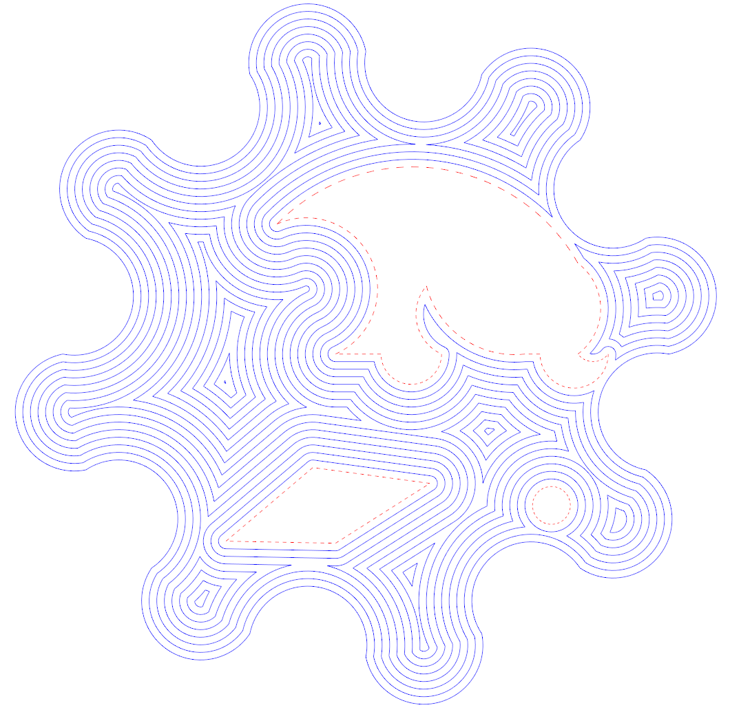
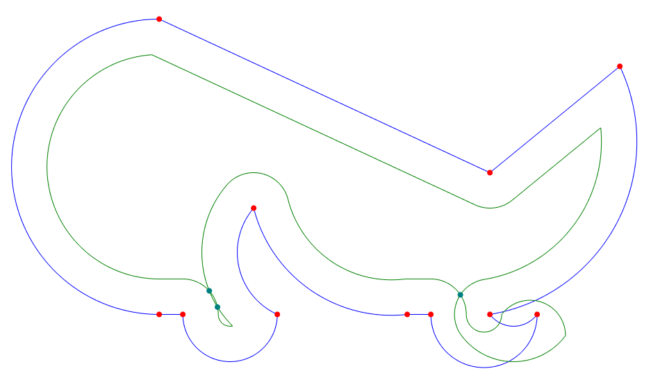
Raw offset polyline self intersects (dark cyan) (Step 4)

Raw Offset Polyline Intersects

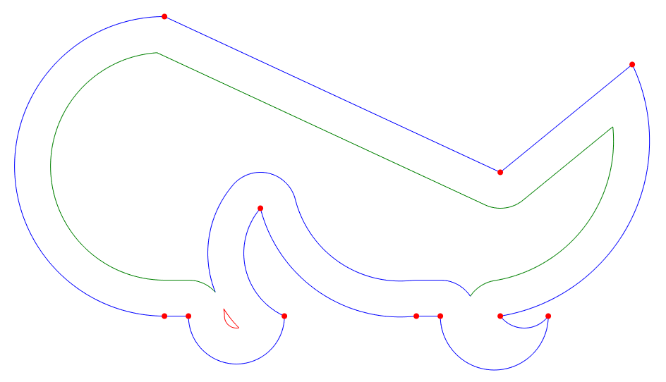
Valid open polyline slices created from self intersects (in green, red, and blue) (Step 5 & 6)

Valid Slices

Open polyline slices stitched together (in red and blue) (Step 7)

Final Output Polylines

Interactively Exploring the Algorithm

An interactive UI app (implemented using Qt and QML) is available (CavalierContoursDev) to visualize and explore in real time the offset algorithm. This app is also compiled to web assembly, for the live web version go here. The app was used to generate all the images in this markdown.

Performance

The implementation is not entirely geared around performance but some profiling has been done to determine where to reserve memory up front and avoid trig functions where possible. I suspect there is quite a bit of performance to be gained in using a custom memory allocator, and there may be ways to modify the algorithm to prune invalid segments faster.

Additionally the structures and control flow are factored for readability/maintainability and may be limiting how much is compiled to simd instructions.

Benchmarks

The following is a series of benchmarks that were run on windows 10 64 bit with an i7 6700k @ 4.00Ghz, code was built using MSVC 2019 compiler version 19.24.28314 targeting 64 bit (similar results were found using MingGW 7.3 64 bit). Each benchmark profile has different characteristics, and each profile is repeatedly offset both inward and outward with increasing delta.

All offsets were performed with rounded joins (maintaining exact offset distance from original input), and 1e8 was used to scale the double inputs into 64 bit integers for input into the Clipper library (but scaling and copying is not included in the benchmarks to avoid penalizing Clipper). Offsets are always computed from the original input (not from previous offset results) to avoid the explosion of vertexes from rounded joins approximated by line segments created by Clipper.

  • BM_square is a simple square with 4 edges.
  • BM_circle is a simple circle defined by two vertexes with bulge = 1 (half circle arcs).
  • BM_roundedRectangle is a rectangle with corner radii.
  • BM_Profile1 is a small closed polygon with 4 arcs and 2 line segments.
  • BM_Profile2 is a slightly larger closed polygon with 7 arcs and 4 line segments.
  • BM_PathologicalProfile1/N is a circle whose perimeter is composed of half circle arcs alternating clockwise and counter clockwise. N is the number of half circles that make up the perimeter. This is a pathological input for 2d bounding box spatial indexing: as the offset delta increases all of the raw offset segment's bounding boxes start to overlap, and all of the segments start to intersect.

1e-2 (0.01) and 1e-3 (0.001) at the end of "arcs approx." refers to the error when approximating an arc as a series of line segments, it is the maximum allowed distance between the approximating line segments and the original arc. Note the profile vertex distances are in the range of 0-50 so the 1e-2 (0.01) error is intolerable for many applications, but significantly cuts down on the number of generated segments.

benchmark vertex count arcs approx. 1e-2 vertex count arcs approx. 1e-3 vertex count
BM_square 4 4 4
BM_circle 2 142 446
BM_roundedRectangle 8 56 164
BM_Profile1 6 80 241
BM_Profile2 11 162 494
BM_PathologicalProfile1/10 10 400 1240
BM_PathologicalProfile1/25 25 625 1975
BM_PathologicalProfile1/50 50 900 2800
BM_PathologicalProfile1/100 100 1300 4000

All times are wall time. Exact details of the benchmark profiles and offsets run can be found under the dev project here. For more on the clipper library see [11].

CavalierContours (Arcs Approximated) vs. Clipper

benchmark cavc arcs approx. 1e-2 (ms) clipper arcs approx. 1e-2 (ms) cavc vs. clipper
BM_square 0.21 0.72 3.5x
BM_circle 9.11 9.47 1.0x
BM_roundedRectangle 3.92 8.46 2.2x
BM_Profile1 8.55 6.33 0.7x
BM_Profile2 17.57 16.59 0.9x
BM_PathologicalProfile1/10 34.97 136.46 3.9x
BM_PathologicalProfile1/25 70.93 241.95 3.4x
BM_PathologicalProfile1/50 138.17 514.95 3.7x
BM_PathologicalProfile1/100 336.37 1347.09 4.0x
benchmark cavc arcs approx. 1e-3 (ms) clipper arcs approx. 1e-3 (ms) cavc vs. clipper
BM_square 0.21 1.71 8.1x
BM_circle 38.04 61.37 1.6x
BM_roundedRectangle 13.14 61.61 4.7x
BM_Profile1 27.07 24.44 0.9x
BM_Profile2 52.64 73.64 1.4x
BM_PathologicalProfile1/10 109.96 1383.46 12.6x
BM_PathologicalProfile1/25 227.51 2824.67 12.4x
BM_PathologicalProfile1/50 385.46 6170.26 16.0x
BM_PathologicalProfile1/100 821.15 15797.60 19.2x

The above benchmarks were taken by converting all arcs to line segments before running the profile through the offsetting algorithm. Even with no arcs in the input CavalierContours is competitive with a noticeable speedup in many cases. This is in part due to CavalierContours not having to construct rounded joins from line segments (an exact arc can be constructed instead).

CavalierContours (Arcs Included) vs. Clipper

benchmark cavc w/ arcs (ms) clipper arcs approx. 1e-2 (ms) cavc vs. clipper
BM_square 0.21 0.72 3.4x
BM_circle 0.12 9.47 76.4x
BM_roundedRectangle 0.49 8.46 17.3x
BM_Profile1 0.76 6.33 8.4x
BM_Profile2 1.55 16.59 10.7x
BM_PathologicalProfile1/10 1.61 136.46 84.9x
BM_PathologicalProfile1/25 7.17 241.95 33.8x
BM_PathologicalProfile1/50 23.98 514.95 21.5x
BM_PathologicalProfile1/100 85.10 1347.09 15.8x
benchmark cavc w/ arcs (ms) clipper arcs approx. 1e-3 (ms) cavc vs. clipper
BM_square 0.21 1.71 8.1x
BM_circle 0.12 61.37 494.7x
BM_roundedRectangle 0.49 61.61 126.1x
BM_Profile1 0.76 24.44 32.3x
BM_Profile2 1.55 73.64 47.6x
BM_PathologicalProfile1/10 1.61 1383.46 861.0x
BM_PathologicalProfile1/25 7.17 2824.67 394.2x
BM_PathologicalProfile1/50 23.98 6170.26 257.3x
BM_PathologicalProfile1/100 85.10 15797.60 185.6x

The above benchmarks compare CavalierContours taking in the original input (arcs included) vs. Clipper (arcs must be approximated). The performance benefits of processing the arcs directly is quickly realized.

Implementation Notes and Variations

Float Comparing and Thresholding

When comparing two float values for equality, a and b, this implementation uses a simple fuzzy comparing method of abs(a - b) < epsilon, where epsilon is a very small number, e.g. 1e-8 or 1e-5 depending on the context. These numbers were picked through anecdotal use case trial/error where input values are typically between 0.1 and 1000.0. If finer comparisons are required, or if the input values get quite large or small then numerical stability issues may arise and the means of fuzzy comparing will need to be adjusted. See mathutils.hpp for c++ implementation.

Joining Raw Offset Segments

When joining raw offset segments together the current implementation always uses an arc to connect adjacent segments if they do not intersect, the arc maintains a constant distance from the original input polyline. Alternatively these joins could be done by extending the original line/arc segments until they intersect or by some other means entirely. Note that any other type of join will result in the offset polyline not being at a constant offset distance from the original input.

Stitching Open Polylines

When stitching the open polylines together the current implementation only looks to stitch end points to start points. This assumes that the slices will always stitch together this way, this is a valid assumption if all slices are from the same raw offset polyline, but in the case that you want to stitch slices from different offsets together the implementation must look at both start and end points since directionality may change.

When stitching open polylines together the current implementation attempts to stitch the slices into the longest polylines possible (there are multiple possibilities when slices become coincident or tangent at end points with one another). Alternatively one could implement it in a way to stich slices into the shortest polylines possible. This may be useful if in the case of coincident stretches the result should be marked or discarded.

Development

Pull requests, feature requests/ideas, issues, and bug reports are welcome. Please attempt to follow the code style and apply clang-format (using the .clang-format file) before making a pull request.

API Stability

There is not an official release yet - all functions and structures are subject to change. This repository for now serves as an implementation reference that is easy to understand and possibly transcribe to other programming languages. The code can be used as is, but there is no guarantee that future development will maintain the same functions and structures. Ideas/pull requests for what a stable API interface should look like are welcome.

Tentatively the C API is stable, see header file here, but has not yet been solidified in a 1.0 release.

Project Motivation and Goal

I set out to generate tool compensated milling tool paths for profile cuts, in the process I found many papers on offsetting curves for CAD/CAM uses [1][9][10][16], but there is often no reference implementation. Most algorithms described are dense and difficult to reproduce. Issues such as numeric stability, how to handle coincident segments, process collapsing arcs, etc. are often not mentioned, and the algorithmic description detail is inconsistent. It may be very clear how to perform some of the steps, but other steps are quickly glossed over, and it becomes unclear how to go about implementing. All of these issues would not be much of a problem if an open source reference implementation was supplied, but for all the papers I have read not a single implementation was given.

In addition to papers being difficult to utilize as a pragmatic tool, most papers focus on offsetting straight segment polylines or polygons (sometimes referred to as point sequence curves) [9][10][16]. And there are a few notable open source libraries that work only on straight segment polylines as well [11][12][13]. Unfortunately if only straight segments are supported then all curves, even simple constant radius arcs, must be approximated using straight segments. This leads to an inefficient memory footprint, and additional algorithmic steps if arcs must be reconstructed from points after offsetting. Constant radius arcs are very common in CAD/CAM applications (tool compensation, tool offsetting for cleanout, part sizing, etc.), and arcs may be used to approximate other types of curves more memory efficiently than straight line segments, e.g. for Bezier curves [14].

There are a few papers on offsetting curves with arc segments [1][15], some involve a Voronoi diagram approach [15], and others are more similar to the approach this library takes by processing self-intersects and applying a clipping algorithm [1]. These papers do not provide an opensource reference implementation, and many of them are difficult to understand, and even more difficult to reproduce.

The goal of this project is to provide a simple, direct, and pragmatic algorithm and reference implementation for polyline offsetting (supporting both lines and arcs, open and closed) for use in CAD/CAM applications. It includes the minimum computational geometry building blocks required (vectors, spatial indexing, etc.) to accomplish this goal. The code is written with the intent that it can be easily read, modified, and transcribed to other programming languages. The interactive UI app can be used to help understand the algorithm visually and make parts of the code easier to digest.

Algorithm Complexity and 2D Spatial Indexing

The algorithm requires finding self-intersects, testing the distance between points and the original polyline, testing for intersects between new segments and the original polyline, and stitching open polylines together end to end. The naïve approach to such steps typically results in O(n2) algorithmic complexity where each segment must be tested against every other segment and each point must be tested against every segment.

The approach used by this library is to use a packed Hilbert R-Tree [3]. See staticspatialindex.hpp for c++ implementation. See [4] and [5] for more implementation references. This results in an algorithm complexity of O(n log n) for typical inputs, with worse case O(n2) for pathological inputs.

Packed Hilbert R-Tree

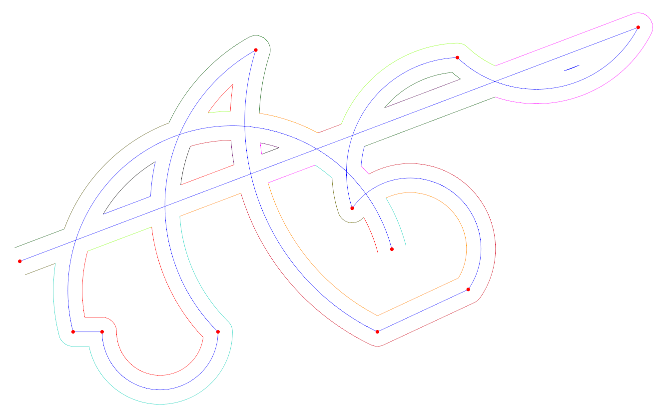
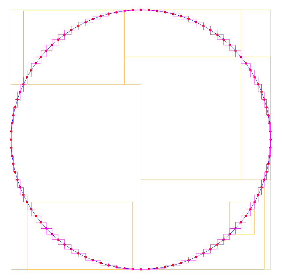
Here is an image of a closed polyline approximating a circle using 100 line segments (blue lines and red vertexes) with spatial index bounding boxes made visible (magenta, orange, and light green boxes). The root of the R-Tree is the light green box, its children are the orange boxes, and its grand children are the magenta boxes.

Simple Spatial Index

The packed Hilbert R-Tree is very fast to build and query, but requires rebuilding the tree anytime the data changes – however for computational geometry algorithms such as those performed in this library we start with no indexed data, and our data does not change for the duration of the algorithm, making the tradeoff ideal for the use case.

There are alternative approaches, e.g. by combining an Interval Tree [6] and binary heap [7] a sweep line algorithm [8] approach can be taken to avoid O(n2) complexity.

Note that there are pathological input cases that will still result in O(n2) behavior even with a spatial index or sweep line algorithm. E.g. a polyline for which all segments have axis-aligned bounding boxes that overlap. But for common inputs seen in CAD/CAM applications this is not the case, and a run time complexity of O(n log n) will result.

References

[1] Liu, X.-Z., Yong, J.-H., Zheng, G.-Q., & Sun, J.-G. (2007). An offset algorithm for polyline curves. Computers in Industry, 58(3), 240–254. doi:10.1016/j.compind.2006.06.002

[2] Bulge conversions: http://www.lee-mac.com/bulgeconversion.html

[3] https://en.wikipedia.org/wiki/Hilbert_R-tree#Packed_Hilbert_R-trees

[4] JavaScript spatial index implementation: https://github.com/mourner/flatbush/

[5] Fast 2D to 1D Hilbert curve mapping used for spatial index: https://github.com/rawrunprotected/hilbert_curves

[6] https://en.wikipedia.org/wiki/Interval_tree

[7] https://en.wikipedia.org/wiki/Binary_heap

[8] https://en.wikipedia.org/wiki/Sweep_line_algorithm

[9] Lin, Z., Fu, J., He, Y., & Gan, W. (2013). A robust 2D point-sequence curve offset algorithm with multiple islands for contour-parallel tool path. Computer-Aided Design, 45(3), 657–670. doi:10.1016/j.cad.2012.09.002

[10] Kim, D.-S. (1998). Polygon offsetting using a Voronoi diagram and two stacks. Computer-Aided Design, 30(14), 1069–1076. doi:10.1016/s0010-4485(98)00063-3

[11] Clipper library: http://www.angusj.com/delphi/clipper.php (github fork here: https://github.com/jbuckmccready/clipper-lib)

[12] CGAL library for offsetting polylines: https://doc.cgal.org/latest/Straight_skeleton_2/index.html

[13] Boost geometry: https://www.boost.org/doc/libs/1_53_0/libs/geometry/doc/html/index.html

[14] Bezier biarc approximating: https://github.com/domoszlai/bezier2biarc

[15] Held, M., & Huber, S. (2009). Topology-oriented incremental computation of Voronoi diagrams of circular arcs and straight-line segments. Computer-Aided Design, 41(5), 327–338. doi:10.1016/j.cad.2008.08.004

[16] Kim, H.-C., Lee, S.-G., & Yang, M.-Y. (2005). A new offset algorithm for closed 2D lines with Islands. The International Journal of Advanced Manufacturing Technology, 29(11-12), 1169–1177. doi:10.1007/s00170-005-0013-1

cavaliercontours's People

Contributors

jbuckmccready avatar karl-nilsson avatar martijuerg avatar svenpilz avatar

Stargazers

 avatar  avatar  avatar  avatar  avatar  avatar  avatar  avatar  avatar  avatar  avatar  avatar  avatar  avatar  avatar  avatar  avatar  avatar  avatar  avatar  avatar  avatar  avatar  avatar  avatar  avatar  avatar  avatar  avatar  avatar  avatar  avatar  avatar  avatar  avatar  avatar  avatar  avatar  avatar  avatar  avatar  avatar  avatar  avatar  avatar  avatar  avatar  avatar  avatar  avatar  avatar  avatar  avatar  avatar  avatar  avatar  avatar  avatar  avatar  avatar  avatar  avatar  avatar  avatar  avatar  avatar  avatar  avatar  avatar  avatar  avatar  avatar  avatar  avatar  avatar  avatar  avatar  avatar  avatar  avatar  avatar  avatar  avatar  avatar  avatar  avatar  avatar  avatar  avatar  avatar  avatar  avatar  avatar  avatar  avatar  avatar  avatar  avatar  avatar  avatar

Watchers

 avatar  avatar  avatar  avatar  avatar  avatar  avatar  avatar  avatar  avatar  avatar  avatar  avatar  avatar  avatar  avatar  avatar  avatar

cavaliercontours's Issues

Apparently incorrect output using ParallelOffsetIslands

Hello,

first of all, great work. Your library is impressive.

I'm starting using it to understand the potentialities.

I'm looking at the ParallelOffsetIslands. I created a small test in which I have three profiles (one outer profile and two islands). The coordinates of the profiles are as follows:

island 1:
(20,20)
(20,40)
(40,40)
(40,20)
IsClosed() = true;

island 2:
(60,30)
(60,80)
(80,80)
(80,30)
IsClosed() = true;

outer contour:
(0,0)
(100,0)
(100,100)
(0,100)
IsClosed() = true;

Then I followed exaclty the steps reported here:
https://github.com/jbuckmccready/CavalierContours/blob/master/examples/polylineoffsetislands.cpp

to perform the offset of the input profiles. However, I get a strange result that is (the blue profiles are the input ones, while the green are the output ones):
output_cavc_1
In the output I get 2 profiles (the smaller one and the bigger that includes both the offset of the bigger island and the offset of the outer contour), but I would expect 3 profiles if the coincident segments are not discarded.
Or, I would expect something like:
expected_output
Maybe I am missing something? or it is a bug?

Curves difference problem

Hello and compliments again for your work!

Recently one curves difference operation produced an unexpected result. According to the following image:

Untitled

I was computing the difference between the white line and the red line. The result has been translated 100 units in the y direction and drawn in green. The problem is that all what is left of the red "circle" is missing.

I tried to simplify the problem before publishing here, but as soon as I make small variations in input data the problem disappears...

That's why I'm attaching the raw data. Each line represents x, y, bulge of a vertex, the white line is on top, the red follows.

Thanks. L

563.775100244278 424.220150044019 0
576.860340670299 431.922000322341 -0.190218373487698
587.741076274678 433.633775050241 0
594.252489848897 432.178361231882 -0.18796247568131
603.294793423897 426.104475216784 0.110232815239728
651.216922681117 382.03851414704 -0.0137758363314688
651.920806164343 381.605531451554 0.108051353945198
666.922392086524 375.894478129712 -0.0820686709936642
671.577042425504 374.391866576656 0
690.326772987839 364.725000997945 0.100989586864969
698.52021110662 362.415604128012 0
701.285110378745 362.212197084576 -0.0805249311883016
705.954499347671 361.098487393067 0
745.56159576432 344.593186309873 -0.193821485444316
756.726145100352 345.581773314346 0
773.265853905451 340.563524507768 -0.273133458262753
787.856523016433 345.000213060298 0.0854677144777862
865.293982361801 339.761648185311 0.0130143782013616
844.750393065621 341.131435438289 0
820.878347715259 342.10000835824 -0.273598391484826
808.058970122095 350.401663325378 0
807.561967172104 351.399791287742 0.224295029889714
806.10932126658 352.544792761443 0.0379623113730011
804.880141864589 352.730993120664 0
771.005463169894 355.257710363912 -0.327249285592904
757.520623594488 366.77773970541 0.455225314296193
749.99212561602 370.746383022071 -0.271623459839902
735.011277905873 373.182396732415 0
719.668303868857 372.686094577875 -0.187566572970122
709.413658834857 376.296111803669 0
708.29977711401 377.252195515701 0.163342832864542
707.997473825034 377.374866980091 0
676.93278245763 379.292789107644 -0.132535668110463
669.527509773639 381.789601931447 0
667.356794441608 383.239034304494 -0.218493033341439
660.797189977336 393.89399369015 0
660.090463903118 399.676525428431 -0.2219870554849
664.026504726362 411.744565933748 0.0673180016113658
653.38422092449 417.130006696963 0
643.340296721685 420.615659002564 -0.156614660928744
636.009601183204 426.127902625301 0.116279710522012
614.205198006436 445.403873203374 0.248824877823294
584.004634641804 445.544695039742 0.0834463578326797
565.057827004872 431.15353751968 -0.0121681077925243
564.544948960788 430.634091127567 0.355940646831284

726.621074799823 374.75174833362 0
736.05375302248 374.008553753542 -0.193978199096541
738.062071964538 373.008967210915 0
743.846007511413 366.49065666404 -0.231482029859072
744.55133990716 363.950245251734 0
743.071237368098 356.002827038844 -0.0836239131013011
742.728609579215 355.067062639497 -1.38250253537883
725.172581353511 374.504915741864 -0.124340948711381

Offset bug?

Hello,

I'm sure I hit an offset bug already resolved in this library.

Can you please confirm that these missing nested offsets were fixed in this or in the Rust version of this library?

image

Removing some nesting levels, everything works fine.

image

Just in case, do you remember the changeset?

Thank you.

Improve Performance of Island Offsetting

Currently the island offsetting algorithm uses spatial indexes on all of the offset loops for finding intersects. For repeated offsetting the previous spatial indexes can be reused for the next parallel offset.

There may also be some easy changes that reduce the number of memory allocations.

Add Implementation for Combining Closed Polylines

Given two closed non-self intersecting polylines that overlap one another find a new polyline that describes their combined outline. This is equivalent to a Boolean AND operation on polygons.
Implementation likely involves finding intersects between polylines, discarding internal slices, and stitching slices together at intersect points.

Add Functions to Track Offset Segment Origins

When performing parallel offsets each offset is composed of offset slices which originate from particular polyline segments. These origins can be tracked for use in traversing between the offset curves (e.g. in the case of a tool path milling operation).

The origins can be represented as vertex index range mappings, e.g. (1-2) -> (1-3) would mean the offset segments formed by the vertexes at index 1 to index 2 originated from the segments formed by the vertexes at index 1 to index 3.

The parallel offset functions be be improved to keep track and return these mappings in addition the the resulting polyline offset.

Not clipped polyline after offset

After offset operation if the new polyline self intersected, the intersected edges clipped and created polylines more than one.
Is that possible to get the intersected polyline without clipping?

Multiple combining polylines

Is there a way to make multi combining on polylines like clipper's AddPaths.

Initially i have 1 polyline, after offset i get multi polylines and i want to cut (cavc::PlineCombineMode::Exclude)
these polylines by more than one islands.

(Question) Smooth offset contour

Hi and many thanks for this great library.
I would like to try to generate a smooth offset contour, with at best only tangential connections.
The offset contour on an rectangle island is already a good result. I know this comes from the fact that the offset lines are connected by an arc. The same could be also done by all of the others too.
So my question would be, could you point me a place where the arc calculation is done and where the "smooth" algorithm could be placed?

BR Manuel

bulge factor

Thank you for your excellent work !

I have a little issue going on.

Why must the bulge factor between -1 and 1? I have arc's with higher bulge value's. This higher or lower value occur's when the arc center goes inside the arc segment.

This is the terminal output of your script : bulge should always be between -1 and 1"' failed.

In some cases an arc has a bulge factor of 7 or -7. See this example : http://people.fsv.cvut.cz/www/chourpav/Lisp/Chapter%2011.htm , and then figure 11.5

So far, i think i am correct. please correct me if this is not the case.

Can you provide a example how to calculate the bulge factor for an arc of 270 degrees with a output between -1 and 1?
Thank you !

Another tiny thing to consider : island.addVertex(it3->x, it3->y, 0);
Can you provide a : islands.clear(); to empty the vector?

This is my output so far.
https://forum.linuxcnc.org/media/kunena/attachments/23278/cadcam_pocket_with_islands1.png

Not closed polyline abnormal with large offset

cavc::Polyline input;
//add points to input
for (size_t i = 0; i < PX.size(); i++)
{
input.addVertex(PX[i], PY[i], 0);
}
input.isClosed() = false;
double offset = 150;
std::vector<cavc::Polyline> results = cavc::parallelOffset(input, offset);

When I set the offset to 3, the result is correct.
But when I set the offset greater than 20, I can't get the correct curve.
Here's the data I use.
PX.txt
PY.txt
Please give me some advice.

Integrating new curve types

Great library! I do have a question related to #19. How easy would it be to extend CavalierContours with new curve kinds (e.g. rational B-splines). BTW: I'm looking for a 2D geometric kernel with boolean ops and offset functionality.

combinePolylines() in PlineCombineMode::Exclude mode with touching shapes can result in no output

I am working on integrating the CavalierContours into my project that demonstrates various geometric algorithm libraries and their ability to perform boolean operations on as well as offsetting of polygons/polylines. Here is a link to the project:

https://github.com/fdarling/line-arc-offset-demo

When running some tests I ran into a bug with the Exclude operation. If I subtract a vertical round-capped line from a horizontal rounded rectangle, it works quite nicely. However if I subtract the vertical round-capped line from the results (should do nothing, it's already been subtracted), it results in no geometry for the lower half of the vertical line.

Perhaps I am misunderstanding something in the API, but I don't think so because many other more complex test cases are succeeding. I'd appreciate any insight!

Pasted further down is a standalone C++ test case that illustrates the problem. It subtracts one Polyline from another (minuend - subtrahend), resulting in two Polylines. It then takes those resulting Polylines and subtracts the subtrahend from them once more, which should do nothing, but somehow it annihilates one of the original results.

Further down in the test case code I repeat the problematic subtraction with the Polylines hard-coded so that the issue can be narrowed down more easily. In other words, the second test is all that really needs to be debugged.

Here is an image showing the two shapes that I am subtracting. The minuend is in black, and the subrahend is in red:

CavC_Test_Case

Here is the console output of the test case:

---- Subtracting original Polylines ----
excludeResult.remaining.size():  2
excludeResult.subtracted.size(): 0
---- Subtracting resulting Polylines with original subrahend (shouldn't be able to cut anymore) ----
	excludeResult.remaining.size():  1
	excludeResult.subtracted.size(): 0
	----
	excludeResult.remaining.size():  0 (INCORRECT!)
	excludeResult.subtracted.size(): 0
	----
---- Subtracting problematic Polylines (should leave minuend untouched) ----
excludeResult.remaining.size():  0
excludeResult.subtracted.size(): 0

And the source code:

#include <iostream>

#include "cavc/polylinecombine.hpp"

using namespace cavc;

#define KEEP_BULGES

#ifdef KEEP_BULGES
#define ADD_VERTEX(x, y, bulge) addVertex(x, y, bulge)
#else
#define ADD_VERTEX(x, y, bulge) addVertex(x, y, 0)
#endif

int main(int argc, char **argv)
{
    (void)argc;
    (void)argv;
    std::cout << "---- Subtracting original Polylines ----" << std::endl;
    {
        Polyline<double> a;
        a.ADD_VERTEX(-0.105, 0, 0);
        a.ADD_VERTEX(-0.105, 0.5, -1);
        a.ADD_VERTEX(-0.095, 0.5, 0);
        a.ADD_VERTEX(-0.095, 0, -1);
        a.isClosed() = true;

        Polyline<double> b;
        b.ADD_VERTEX(-0.25, 0.235, -0.414214);
        b.ADD_VERTEX(-0.255, 0.24, 0);
        b.ADD_VERTEX(-0.255, 0.29, -0.414214);
        b.ADD_VERTEX(-0.25, 0.295, 0);
        b.ADD_VERTEX(0.25, 0.295, -0.414214);
        b.ADD_VERTEX(0.255, 0.29, 0);
        b.ADD_VERTEX(0.255, 0.24, -0.414214);
        b.ADD_VERTEX(0.25, 0.235, 0);
        b.isClosed() = true;

        CombineResult<double> excludeResult = combinePolylines(a, b, PlineCombineMode::Exclude);
        std::cout << "excludeResult.remaining.size():  " << excludeResult.remaining.size() << std::endl;
        std::cout << "excludeResult.subtracted.size(): " << excludeResult.subtracted.size() << std::endl;
        std::cout << "---- Subtracting resulting Polylines with original subrahend (shouldn't be able to cut anymore) ----" << std::endl;
        for (std::vector< Polyline<double> >::const_iterator it = excludeResult.remaining.begin(); it != excludeResult.remaining.end(); ++it)
        {
            CombineResult<double> excludeResult2 = combinePolylines(*it, b, PlineCombineMode::Exclude);
            std::cout << "\texcludeResult.remaining.size():  " << excludeResult2.remaining.size();
            if (excludeResult2.remaining.size() != 1)
                std::cout << " (INCORRECT!)";
            std::cout << std::endl;
            std::cout << "\texcludeResult.subtracted.size(): " << excludeResult2.subtracted.size() << std::endl;
            std::cout << "\t----" << std::endl;
        }
    }
    std::cout << "---- Subtracting problematic Polylines (should leave minuend untouched) ----" << std::endl;
    {
        Polyline<double> a;
        a.ADD_VERTEX(-0.105, 0.235, 0);
        a.ADD_VERTEX(-0.095, 0.235, 0);
        a.ADD_VERTEX(-0.095, 0, -1);
        a.ADD_VERTEX(-0.105, 0, 0);
        a.isClosed() = true;

        Polyline<double> b;
        b.ADD_VERTEX(-0.25, 0.235, -0.414214);
        b.ADD_VERTEX(-0.255, 0.24, 0);
        b.ADD_VERTEX(-0.255, 0.29, -0.414214);
        b.ADD_VERTEX(-0.25, 0.295, 0);
        b.ADD_VERTEX(0.25, 0.295, -0.414214);
        b.ADD_VERTEX(0.255, 0.29, 0);
        b.ADD_VERTEX(0.255, 0.24, -0.414214);
        b.ADD_VERTEX(0.25, 0.235, 0);
        b.isClosed() = true;

        CombineResult<double> excludeResult = combinePolylines(a, b, PlineCombineMode::Exclude);
        std::cout << "excludeResult.remaining.size():  " << excludeResult.remaining.size() << std::endl;
        std::cout << "excludeResult.subtracted.size(): " << excludeResult.subtracted.size() << std::endl;
    }
    return 0;
}

bulge value error when bulge>1?

Hi,
Thanks for your great work.
Just want to check why the code will show erree when my input |bulge| >1? and when I split this arc to 2 arcs the code works well.Could you please kindly tell me the reason why the |bulge| cant bigger than 1? and what should i can do to deal with the situation when a arc's |bulge|>1? Thanks a lot.
image

How to make a contour with sharp corners instead of arcs?

Hello,

thanks for this highly useful library. Having used it to generate contours for a while to great satisfaction, we found that we need to avoid the rounded corners of contours in some special applications and need sharp angles instead. We are using the cavc::parallelOffset() function to generate contours.

Could you please advise us on where to start modifying the code? I started with case LineSeg2LineSeg2IntrType::False inside lineToLineJoin() which helped me a lot but I'm not sure if this is the right place and may be there are other places to check as well.

Thanks

capture_20210901_111103_001

Make ParallelOffsetIslands more general

Hello JBuck and thanks for your excellent work!

I'm working on your ParallelOffsetIslands algorithm trying to make it more general in two ways:

  1. Handle negative offsets. Here I think I have a result by reversing all polylines before input to your code and swapping cwLoops with ccwLoops. Is it correct?
  2. Handle different offsets for internal contours and external. Here I'm lost... Can you suggest some heuristics?

Thanks. L

boolean operation

Hi,

I create some offset polylines from model (purple lines).
Poly03

My intention is to cut out the polyline parts that are outside of given circle.
I tried intersection (yellow lines), but the circle becomes part of the cutted polylines.
Is there a way to avoid that?
So that remaining curve from cutted polyline will just some open polylines?

Remove Bluge After offset

Hi,
Thanks for the nice library, i just started to try few values.

Not sure if this is a bug or my mistake in code.
Below is the code i'm trying

int main()
{
    Polyline<double> input;
    input.addVertex(0, 0, 0.0);
    input.addVertex(0, 40, 0.0);
    input.addVertex(10, 40, 0.0);
    input.addVertex(10, 10, 0.0);
    input.addVertex(40, 10, 0.0);
    input.addVertex(40, 0, 0.0);

    input.isClosed() = true;
    
    vector<Polyline<double>> results = parallelOffset(input, -2.0);
    vector<PlineVertex<double>> points =  results[0].vertexes();
    for (int i = 0; i < points.size(); i++)
    {
        PlineVertex<double> point = points.at(i);
        cout << "x: " << point.x() << " y: "  << point.y() << " Bluge: "<<point.bulge()<< endl;
    }
}

Below is the output

x: 2 y: 2 Bluge: 0
x: 2 y: 38 Bluge: 0
x: 8 y: 38 Bluge: 0
x: 8 y: 10 Bluge: 0.414214 //Why this Bluge appeared?
x: 10 y: 8 Bluge: 0
x: 38 y: 8 Bluge: 0
x: 38 y: 2 Bluge: 0

Is there a way to make sure we get straight lines after offset?
expected output was :

x: 2 y: 2 Bluge: 0
x: 2 y: 38 Bluge: 0
x: 8 y: 38 Bluge: 0
x: 8 y: 8 Bluge: 0
x: 38 y: 8 Bluge: 0
x: 38 y: 2 Bluge: 0

I have added reference image below.
Reference Offset values

Thanks & Regards
Prakash

Internal offset of a small closed rectangle

Hello JBuck and thanks for your excellent work. I'm looking forward for your stable release. I worked as well on Liu paper and was not able to make it work.

Having said that, I found a bizarre result on a simple case. I have a rectangle defined by (x,y,bulge):
0,0,0
120,0,0
120,40,0
0,40,0
isClosed = true

and asked for the internal offset with offset value = 30. I was expecting an empty list of curves, but a curve was return and it was:

x=22 y=22 bulge=0
x=98 y=22 bulge=0
x=98 y=18 bulge=0
x=22 y=18 bulge=0
isClosed=true

Keep in mind that there is a high probability that I misused your code...

Thanks. Bye

ASSERT -> v1 must not be ontop of v2

Following polyline is giving assert;

Path P;
P.addVertex(30.123475382979791, -17.00000, 0.00000);
P.addVertex(42.000000000000000, -17.00000, 0.00000);
P.addVertex(42.000000000000000, 17.00000, 0.00000);
P.addVertex(30.123475382979798, 17.00000, -0.093311550024413187);
P.addVertex(30.500000000000000, 15.00000, 0.00000);
P.addVertex(30.500000000000000, -15.00000, -0.093311550024413409);
parallelOffset(P, -2.0);

Combining open polylines with dual offsets?

Do you have any thoughts on implementing combining with open polylines?

In my case I need to have two open polylines with dual offsetts. I need to somehow combine the two dual offsets (I do not need to alter the original polyline)

Polyline #1 with dual offsets

Polyline1

Polyline #2 with dual offsets

Polyline2

Overlaying of the two

Polyline3a

Desired Output dual offsets are combined

Polyline3

Do you have any thoughts on this type of scanerio? or any plans on supporting it?

Chris

Offsetting multiple polylines without boundary curve

Hi,
I would like to offset multiple different (but closed) polylines in one step.
It is similar to the example image given in the readme (this one) only that I don't want to specify the outer boundary curve. Hence, only the red dashed islands should be offsetted n steps outwards .
I think it should be doable but I couldn't figure it out (also not with the help of the CavalierContoursDev repo).
So maybe you could give me an advice how to achieve this (if it's possible at all)?

IMPORTANT: Development is continuing in Rust (with C FFI)

I am continuing development of this library in Rust with a C FFI (I do not plan to continue working on it in C++). The Rust repository is here.

This C++ repository will remain but I do not plan to work on it much/if at all. If you would like to maintain this C++ project let me know.

Is there any way to establish the relationship between the original segment(curve btween two PlineVertex) of Polyline and the offset segment of Polyline?

(For some reason)for example ,if segment have color property,and is red, execute cavc::parallelOffset function, I hope to find offset segment corresponding to origin,so i can know the offset segment and what color it is. Of course ,offset segment compare to origin ,maybe start or end point coordenate change or this segment disappear or add a new segment,new segment have a default color.

incorrect bulge value in some cases

Hello!
While performing union of given vectors:

" V1: 0:{3, 7, 0}, 1:{3, 4, 1}, 2:{5, 4, 0}, 3:{5, 7, 1}, CCW"
" V2: 0:{4.31623, 3.05132, 0}, 1:{10.3162, 5.05132, 1}, 2:{9.68377, 6.94868, 0}, 3:{3.68377, 4.94868, 1}, CCW"
Found that we have some troubles for cases, when 2 counturs has arcs with bulge == 1 and same center.

Function "splitAtPoint", called from"sortAndjoinCoincidentSlices" handles case, when v1 equal to point.
Now bulge just copied from v1, but if this slice will be cut later, bulge will be changed.

I used this update locally:

SplitResult<Real> splitAtPoint(PlineVertex<Real> const &v1,
                               PlineVertex<Real> const &v2,
                               Vector2<Real> const &point,
                               Vector2<Real> const pointNext = Vector2<Real>())
........
  } else if (fuzzyEqual(v1.pos(), v2.pos(), utils::realPrecision<Real>())) {
    result.updatedStart = PlineVertex<Real>(point, Real(0));
    result.splitVertex = PlineVertex<Real>(point, v1.bulge());
  } else if (fuzzyEqual(v1.pos(), point, utils::realPrecision<Real>())) {
    result.updatedStart = PlineVertex<Real>(point, Real(0));
    auto radiusAndCenter = arcRadiusAndCenter(v1, v2);
    Vector2<Real> arcCenter = radiusAndCenter.center;
    Real a = angle(arcCenter, pointNext);
    Real arcStartAngle = angle(arcCenter, v1.pos());
    Real theta1 = utils::deltaAngle(arcStartAngle, a);
    Real bulge1 = std::tan(theta1 / Real(4));
    result.splitVertex = PlineVertex<Real>(point, bulge1);
  }

So, we use new parameter "pointNext" to calculate new bulge, if needed.
sortAndjoinCoincidentSlices was updated in this way:
auto split1 = splitAtPoint(v1, v2, intr.point1, intr.point2);

Not sure if this update it totally correct for all cases, it was not properly checked, because now i'm fighting with union of:
" V1: 0:{3, 7, 0}, 1:{3, 4, 1}, 2:{5, 4, 0}, 3:{5, 7, 1}, CCW"
" V2: 0:{4, 3, 0}, 1:{9, 3, 1}, 2:{9, 5, 0}, 3:{4, 5, 1}, CCW"

Could you please check update above and use it, if needed.

Add Implementation for Simultaneous Polyline Offsetting

Add support for defining multiple polylines to apply offsets to and join offsets together. E.g. for use in defining islands inside of a Jordan curve and then applying repeated offsets.
Implementation would likely involve finding intersects between offset polylines and joining them together.

Shifting the input polyline produces very different results

Hello,

first, thanks for the great library. We've been using it to our satisfaction for quite some time. However, we are facing an issue which looks like numeric instability to me. We will appreciate your help. Thanks.

We have a drawing with multiple figures like this (ignore the dashed lines):
capture_20220604_114851_001

We are generating both inner and outer contour for it. It works fine on this closed polyline

X	Y	Bulge
473.760000000000000	123.560000000000000	0.463985680061077
475.033239959260000	138.783314391340000	0.463985680061077
459.809938967064000	137.509914237247000	0.134441584771250
444.227406100013000	140.395488288632000	0.041688391650421
439.303094239882000	139.562816356986000	0.273832882708070
417.687160318691000	117.946814732389000	0.041688391650421
416.854503810494000	113.022500264269000	0.134440937017869
419.740000000000000	97.440000000000000	0.463985680061078
418.466760040740000	82.216685608660400	0.463982482960671
433.690000000000000	83.490000000000000	0.134441734196030
449.272593899987000	80.604511711367700	0.041688391650421
454.196905760118000	81.437183643013500	0.273832882708070
475.812839681309000	103.053185267611000	0.041688391650421
476.645496189506000	107.977499735731000	0.134441734196029
473.759959094621000	123.560084597999000	0.000000000000000

But it fails to generate the inner contour on this closed polyline which differs just by adding 248 to all the X coordinates. The remaining diffs are <~1e-12.

X	Y	Bulge
721.760000000000000	123.560000000000000	0.463985680061079
723.033239959260000	138.783314391339000	0.463985680061078
707.809938967064000	137.509914237247000	0.134441584771250
692.227406100013000	140.395488288632000	0.041688391650421
687.303094239882000	139.562816356986000	0.273832882708070
665.687160318691000	117.946814732389000	0.041688391650422
664.854503810494000	113.022500264269000	0.134440937017869
667.740000000000000	97.440000000000000	0.463985680061077
666.466760040740000	82.216685608660500	0.463982482960672
681.690000000000000	83.490000000000000	0.134441734196030
697.272593899987000	80.604511711367700	0.041688391650421
702.196905760118000	81.437183643013500	0.273832882708070
723.812839681309000	103.053185267611000	0.041688391650421
724.645496189506000	107.977499735731000	0.134441734196029
721.759959094621000	123.560084597999000	0.000000000000000

We worked around this problem by shifting the polyline to [0,0], generate contours and then shift back. Here's the data when shifted to [0,0]

X	Y	Bulge
0.000000000000000	0.000000000000000	0.463985680061079
1.273239959259740	15.223314391339500	0.463985680061078
-13.950061032935700	13.949914237247200	0.134441584771250
-29.532593899986500	16.835488288632300	0.041688391650421
-34.456905760118000	16.002816356986500	0.273832882708070
-56.072839681309000	-5.613185267610900	0.041688391650422
-56.905496189505900	-10.537499735731300	0.134440937017869
-54.020000000000000	-26.120000000000000	0.463985680061077
-55.293239959259800	-41.343314391339500	0.463982482960672
-40.070000000000100	-40.070000000000000	0.134441734196030
-24.487406100013500	-42.955488288632300	0.041688391650421
-19.563094239881900	-42.122816356986500	0.273832882708070
2.052839681309020	-20.506814732389100	0.041688391650421
2.885496189505940	-15.582500264268700	0.134441734196029
-0.000040905378796	0.000084597999020	0.000000000000000

Now it generates a contour but it is not closed - see this picture, ignore the dashed lines:
capture_20220604_120903_002

For your reference, below is the code we used. May be there's something wrong in the way we call the library. We multiply all the coordinates and offset by 10000 prior to calling this function because of previous issues where some contours were not generated completely. And we divide by 10000 after contours are generated. Offset is 0.36 prior to scaling up.

vector<Polyline<double>> CreateContours(Polyline<double> &input, double offset, vector<PlineIntersect<double>>& selfIntersects) {
  // Prune the input polyline of singularities.
  Polyline<double> pruned = pruneSingularities(input, SAME_POINT_EPSILON);

  // Detect self-intersects in the pruned polyline
  selfIntersects.clear();
  if (pruned.size() >= 2) {
    // Spatial index requires at least two points,
    // otherwise the program aborts.
    auto spatialindex = createApproxSpatialIndex(pruned);
    allSelfIntersects(pruned, selfIntersects, spatialindex);
  }

  // compute the resulting offset polylines
  if (selfIntersects.empty()) {
    auto contours = parallelOffset(pruned, offset, false);
    if (contours.size() == 0) {
        // parallelOffset(pruned, offset, true) sometimes does not generate
        // contours due to numeric errors. In such a case, try 
        // parallelOffset(pruned, offset, false) which takes a different code 
        // path and more time but succeeds.
      contours = parallelOffset(pruned, offset, true);
    }
    return contours;
  } else {
    return parallelOffset(pruned, offset, true);
  }
}

It doesn't work only offset=0.5 on specific outerpolyline and island.

Hi,I am doomori.
Thank you very much for wonderful library.

I tried rewrite in interactiveUI/plineoffsetislandsalgorithmview.cpp

cavc::Polyline mainOuterPline;
mainOuterPline.addVertex(0,0,0);
mainOuterPline.addVertex(20,0,0);
mainOuterPline.addVertex(20,20,0);
mainOuterPline.addVertex(0,20,0);
mainOuterPline.isClosed() = true;

and

cavc::Polyline island1;
island1.addVertex(15, 10, 0);
island1.addVertex(17, 10, 0);
island1.addVertex(17, 12, 0);
island1.addVertex(15, 12, 0);
island1.isClosed() = true;
invertDirection(island1);

island is only one,so this code is done on QtCreator
but,
island
this bug?? so it dose not work only offset =0.5,,it work offset =0.4 or offset0.6
I can't understand and resolve,,Please help me.

Thank you .

can you explain the parameters

Hello JBuck and thanks for your excellent work!
I am reading the code, but i have a question that that how to assign the value to the parameters currSliceIndex and available int the folowing code.
avc\polylinecombine.hpp
auto createUnionAndIntersectStitchSelector = [](std::size_t startOfCoincidentSlicesIdx) {
return [=](std::size_t currSliceIndex, std::vectorstd::size_t const &available)

Thanks

Bulge more than 1

Hello @jbuckmccready

I've managed to implement the library with my application.
I have just hit a wall and would like to know if you have a solution for it.

I'm using some arcs that the bulge value ended up being more than 1, it's 1.25 for example.
And one of your checks is to check if the bulge is in between -1 and 1.

Do you have an idea on how to proceed with this?
Should I split the arc into 2, if so would you know the best way to do this?

Thanks,
Denis

Migrate Benchmarks from CavalierContoursDev

I originally planned to have all tests/benchmarks as part of the CavalierContoursDev repository but now think it would be best to consolidate all tests, benchmarks, and examples to this repository. I'm not sure if it makes sense to also move the interactive UI app to this repository as well or keep it separate to minimize clutter.

I would like to have the CMake easily configured to disable/not include benchmarks or tests. And make it easy to use as a build platform for the stable C API, see issue #3.

Glitches on intersection calculation

I stumbled on some glitches while calculating polyline intersections if a polyline intersects the other one in vertex.
Take the following example :

#include "cavc/polyline.hpp"
#include "cavc/polylineintersects.hpp"

#include <iostream>
#include <cmath>

using namespace cavc;

int main(int argc, char *argv[]) {
  (void)argc;
  (void)argv;

  Polyline<double> arc;
  arc.addVertex(0., 1., -std::tan(cavc::utils::pi<double>() / 8));

  // y = 1e-15 works but y = -1e-15 not
  arc.addVertex(1., -1e-15, -std::tan(cavc::utils::pi<double>() / 8));

  arc.addVertex(-1., -1., 0.);
  arc.isClosed() = false;

  Polyline<double> line;
  line.addVertex(-2., 0, 0.);
  line.addVertex(2., 0., 0.);
  line.isClosed() = false;

  cavc::StaticSpatialIndex<double> spatial_index_poly1 = cavc::createApproxSpatialIndex(arc);
  cavc::PlineIntersectsResult<double> intersections;
  findIntersects(arc, line, spatial_index_poly1, intersections);

  std::cout << intersections.intersects.size() << "\n";

  for (auto p : intersections.intersects)
    std::cout << p.pos.x() << " " << p.pos.y() << "\n";

  return 0;
}

On my system, I observe the following behavior using the master branch of cavc:
If the y value of the second vertex of the arc is slightly positive, everything works fine and the correct intersection point is printed. But if y is slightly negative, no intersection is found.

Is this the intended behavior and if so, is there some kind of workaround to overcome this problem?

Please tell me the rule(structure) of parentIndex in parallelOffsetIsland.

Hi,jbuckmccready.I am doomori.
Thank you for good libraly.

Please tell me the rule(structure) of parentIndex in parallelOffsetIsland.
I rewrite that outer Rectangle have 4 simple islands in interactiveUI/plineoffsetislandsalgorithmview.cpp .

mainOuterPline.addVertex(-120,-80,0);
mainOuterPline.addVertex(120,-80,0);
mainOuterPline.addVertex(120,80,0);
mainOuterPline.addVertex(-120,80,0);

and

int count = 4;
for (int i = 0; i < count; ++i)
{
cavc::Polyline island;
island.addVertex(-100+14i, 10, 0);
island.addVertex(-94+14
i, 10, 0);
island.addVertex(-94+14i, 15, 0);
island.addVertex(-100+14
i, 15, 0);
island.isClosed() = true;
invertDirection(island);
m_cwLoops.push_back(std::move(island));
}

and
(in PlineOffsetIslandsAlgorithmView::updatePaintNode)
for (auto const &loop : loopSet.cwLoops) {
printf("cw_parent_Index%zu\n",loop.parentLoopIndex); <-add
addPline(loop.polyline);
}
for (auto const &loop : loopSet.ccwLoops)
{
printf("ccw_parent_Index%zu\n",loop.parentLoopIndex);<-add
addPline(loop.polyline);
}

offset = 2.5
The result is

cw_parent_Index1
cw_parent_Index2
cw_parent_Index3
cw_parent_Index4
ccw_parent_Index0

cw_parent_Index0
ccw_parent_Index0

cw_parent_Index1
ccw_parent_Index0

cw_parent_Index0
ccw_parent_Index0

ccw_parent_Index0

ccw_parent_Index0

In my sence,

cw_parent_Index1 -> 0
cw_parent_Index2 -> 1
cw_parent_Index3 -> 2
cw_parent_Index4 -> 3
ccw_parent_Index0

cw_parent_Index0 any of 0-3
ccw_parent_Index0

cw_parent_Index1 -> 0
ccw_parent_Index0

cw_parent_Index0
ccw_parent_Index0

ccw_parent_Index0

ccw_parent_Index0

Please tell me the rule (structure) of parentIndex about cwLoops.
Thank you .

Why not defined normalizing for zero vector? You can do it.

auto lineVisitor = [&](PlineVertex<Real> const& v1, PlineVertex<Real> const& v2) { result.emplace_back(); PlineOffsetSegment<Real>& seg = result.back(); seg.collapsedArc = false; seg.origV2Pos = v2.pos(); Vector2<Real> edge = v2.pos() - v1.pos(); Vector2<Real> offsetV = offset * unitPerp(edge); seg.v1.pos() = v1.pos() + offsetV; seg.v1.bulge() = v1.bulge(); seg.v2.pos() = v2.pos() + offsetV; seg.v2.bulge() = v2.bulge(); };

v1 and v2 are same after offset. Then it says "normalize not defined for zero vector"

Create Stable C API Release

Create version tags and create a stable C API interface that follows semantic versioning (https://semver.org/). A C API will make it easy to create bindings from other languages and allow for changes and updates to the underlying C++ implementation without breaking users.

A potentially small overhead will be incurred in copying from the C API structures/arrays to the C++ structures but should be negligible for the algorithms being used (offsetting, combining, etc.).

Create Automated Tests

Determine test framework to be used and create automated tests to cover as much of the library as possible. Google test is one possibility but it does not support property based testing out of the box, so I will look into some others.

Some of the functions that need tests are the following:

  • Basic polyline functions (area, path length, extents, winding number, etc.)
  • Polyline offsetting (closed polylines, open polylines, etc.)
  • Polyline combining (union, exclude, intersect, XOR, coincident polylines, etc.)

I would like to create discrete tests (known input and output), as well as property based tests (random but parameterized input with expected properties) to find numeric instabilities, or cases that might not be covered in the discrete tests. The generated data would include the following:

  • Non-self intersecting open and closed polylines
  • Self intersecting open and closed polylines
  • Points inside and outside of generated closed polylines
  • Partially coincident open and closed polylines

idea

Are you interested in auto nesting with cavaliercontours input?

I modified this code : https://github.com/tamasmeszaros/libnest2d to work with Qt.
fixed a bug in the nfpplacer.hpp line 6. Its ready to integrate in the CadCam project now, but i like a change first.

What If we change the backend from clipper into cavaliercontours?

For this i made a ready to go QT project :
https://github.com/grotius-cnc/QT_Nest_with_clipper_backend/blob/master/README.md

the file particleswarm.hpp has some warnings.

Let me know how you think about it.

Recommend Projects

  • React photo React

    A declarative, efficient, and flexible JavaScript library for building user interfaces.

  • Vue.js photo Vue.js

    🖖 Vue.js is a progressive, incrementally-adoptable JavaScript framework for building UI on the web.

  • Typescript photo Typescript

    TypeScript is a superset of JavaScript that compiles to clean JavaScript output.

  • TensorFlow photo TensorFlow

    An Open Source Machine Learning Framework for Everyone

  • Django photo Django

    The Web framework for perfectionists with deadlines.

  • D3 photo D3

    Bring data to life with SVG, Canvas and HTML. 📊📈🎉

Recommend Topics

  • javascript

    JavaScript (JS) is a lightweight interpreted programming language with first-class functions.

  • web

    Some thing interesting about web. New door for the world.

  • server

    A server is a program made to process requests and deliver data to clients.

  • Machine learning

    Machine learning is a way of modeling and interpreting data that allows a piece of software to respond intelligently.

  • Game

    Some thing interesting about game, make everyone happy.

Recommend Org

  • Facebook photo Facebook

    We are working to build community through open source technology. NB: members must have two-factor auth.

  • Microsoft photo Microsoft

    Open source projects and samples from Microsoft.

  • Google photo Google

    Google ❤️ Open Source for everyone.

  • D3 photo D3

    Data-Driven Documents codes.