GithubHelp home page GithubHelp logo

openeew / openeew-sensor Goto Github PK

View Code? Open in Web Editor NEW
42.0 11.0 13.0 34.45 MB

Hardware for an OpenEEW sensor

Home Page: https://openeew.com/docs/build-sensor

License: Apache License 2.0

earthquakes eew sensor iot seismology accelerometer call-for-code linux-foundation openeew hacktoberfest

openeew-sensor's Introduction

Slack License CCBYSA

logo

if you are interested in buying openeew sensor boards, please contact [email protected]


Let's create earthquake early-warning (EEW) systems for every seismically-vulnerable community in the world!

OpenEEW is an initiative by Grillo, IBM and The Linux Foundation to create low cost, open source, IoT-based earthquake early warning systems (EEWs).

This includes

  • Entire archive of unprocessed accelerometer data from Mexico, Chile, and other countries, including earthquakes records with magnitudes above 7 and recorded at different distances
  • Algorithms for the detection and characterization of earthquakes in real time
  • Software examples for creating your own EEW server
  • Hardware designs and firmware so you can build your own IoT-based seismic sensors
  • Application software so that users can receive your alerts via mobile apps, devices and more
  • Guidance to help with your project including deployment of sensors, installations, and more

What is an Earthquake Early-Warning (EEW)?

An earthquake early-warning (EEW) system is a set of technologies that detect and characterize a significant earthquake, rapidly sending the information to nearby communities, before the shaking arrives, so that they can prepare and act appropriately.

Only some governments have attempted to build EEWs due to the incredibly high-cost of traditional seismometers, dedicated telecommunications, and bespoke software.

openeeew-diagram

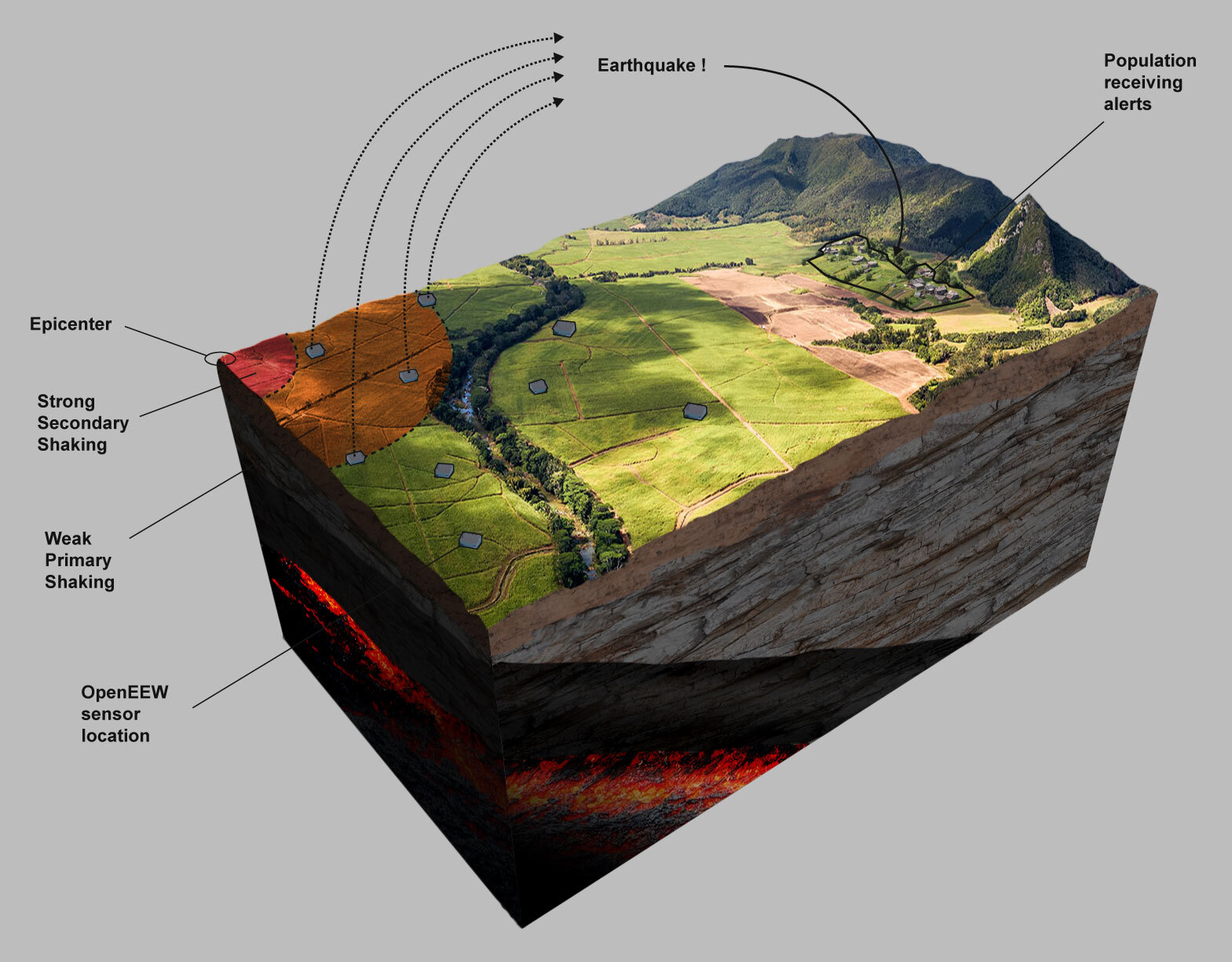
Grillo has already demonstrated that an IoT-based approach to EEW systems is not only within the reach of many global citizens, but performs as well if not better than some government-run systems.

OpenEEW is a Call for Code® with The Linux Foundation project that features a set of core Grillo EEW components; hardware, software and know-how, that will place effective EEWs to be within the reach of many underserved communities around the world.

All OpenEEW projects require the following components:

  • A network of OpenEEW sensors. You can build your own, or buy here. sensor

  • A detection system running on a server. We host a global dashboard that monitors everyone's devices and reports events. detection

  • A method for sending alerts. For example, to a Twitter account, a mobile app, or an IoT device. alarm

Getting Started

Start by reading the Wiki to get your sensor device up and running.

You are also welcome to join our Slack channel and get to know the community, here we discuss issues in real-time.

Contributing

Please read our contribution guidelines for details of how you can get involved, and Code of Conduct for information about how to participate.

Authors

  • Grillo - Initial work - Grillo

Enjoy! Give us feedback if you have suggestions on how to improve this information.

License

This project is licensed under the Apache Software License, Version 2, unless otherwise stated. Separate third party code objects invoked within this code pattern are licensed by their respective providers pursuant to their own separate licenses. Contributions are subject to the Developer Certificate of Origin, Version 1.1 (DCO) and the Apache Software License, Version 2.

OpenEEW data on AWS is licensed under CC BY-SA 4.0.

openeew-sensor's People

Contributors

andygrillo avatar ferdymercury avatar johnwalicki avatar krook avatar perigoso avatar

Stargazers

 avatar  avatar  avatar  avatar  avatar  avatar  avatar  avatar  avatar  avatar  avatar  avatar  avatar  avatar  avatar  avatar  avatar  avatar  avatar  avatar  avatar  avatar  avatar  avatar  avatar  avatar  avatar  avatar  avatar  avatar  avatar  avatar  avatar  avatar  avatar  avatar  avatar  avatar  avatar  avatar  avatar  avatar

Watchers

 avatar  avatar  avatar  avatar  avatar  avatar  avatar  avatar  avatar  avatar  avatar

openeew-sensor's Issues

Stops running after reprogramming

A device A8032A4DD650 used on a testBoard and is screwed down : after reprogramming it runs successfully.

Works first time after programming,(flash-openeew.sh) it with openeew-firmware151
flash-openeew.sh.txt

but after a power cycle stops jumping to main, just cycles.

[2021-05-26 15:05:24] rst:0x10 (RTCWDT_RTC_RESET),boot:0x16 (SPI_FAST_FLASH_BOOT)
[2021-05-26 15:05:24] configsip: 0, SPIWP:0xee
[2021-05-26 15:05:24] clk_drv:0x00,q_drv:0x00,d_drv:0x00,cs0_drv:0x00,hd_drv:0x00,wp_drv:0x00
[2021-05-26 15:05:24] mode:DIO, clock div:2
[2021-05-26 15:05:24] load:0x3fff0018,len:4
[2021-05-26 15:05:24] load:0x3fff001c,len:1044
[2021-05-26 15:05:24] load:0x40078000,len:10124
[2021-05-26 15:05:24] load:0x40080400,len:5828
[2021-05-26 15:05:24] csum err:0x6c!=0x4d
[2021-05-26 15:05:24] ets_main.c 371
[2021-05-26 15:05:24] ets Jun 8 2016 00:22:57
[2021-05-26 15:05:24]
[2021-05-26 15:05:24] rst:0x10 (RTCWDT_RTC_RESET),boot:0x16 (SPI_FAST_FLASH_BOOT)
[2021-05-26 15:05:24] configsip: 0, SPIWP:0xee
[2021-05-26 15:05:24] clk_drv:0x00,q_drv:0x00,d_drv:0x00,cs0_drv:0x00,hd_drv:0x00,wp_drv:0x00
[2021-05-26 15:05:24] mode:DIO, clock div:2
[2021-05-26 15:05:24] load:0x3fff0018,len:4
[2021-05-26 15:05:24] load:0x3fff001c,len:1044
[2021-05-26 15:05:24] load:0x40078000,len:10124
[2021-05-26 15:05:24] load:0x40080400,len:5828
[2021-05-26 15:05:24] csum err:0x4e!=0x4d
[2021-05-26 15:05:24] ets_main.c 371
[2021-05-26 15:05:24] ets Jun 8 2016 00:22:57

left running, 5hours later still not jumped

[2021-05-26 20:36:30] rst:0x10 (RTCWDT_RTC_RESET),boot:0x16 (SPI_FAST_FLASH_BOOT)
[2021-05-26 20:36:30] configsip: 0, SPIWP:0xee
[2021-05-26 20:36:30] clk_drv:0x00,q_drv:0x00,d_drv:0x00,cs0_drv:0x00,hd_drv:0x00,wp_drv:0x00
[2021-05-26 20:36:30] mode:DIO, clock div:2
[2021-05-26 20:36:30] load:0x3fff0018,len:4
[2021-05-26 20:36:30] load:0x3fff001c,len:1044
[2021-05-26 20:36:30] load:0x40078000,len:10124
[2021-05-26 20:36:30] load:0x40080400,len:5828
[2021-05-26 20:36:30] csum err:0x6d!=0x4d
[2021-05-26 20:36:30] ets_main.c 371

Powered off, tried again a couple of days later

[2021-05-28 11:49:24] rst:0x10 (RTCWDT_RTC_RESET),boot:0x16 (SPI_FAST_FLASH_BOOT)
[2021-05-28 11:49:24] configsip: 0, SPIWP:0xee
[2021-05-28 11:49:24] clk_drv:0x00,q_drv:0x00,d_drv:0x00,cs0_drv:0x00,hd_drv:0x00,wp_drv:0x00
[2021-05-28 11:49:24] mode:DIO, clock div:2
[2021-05-28 11:49:24] load:0x3fff0018,len:4
[2021-05-28 11:49:24] load:0x3fff001c,len:1044
[2021-05-28 11:49:24] load:0x40078000,len:10124
[2021-05-28 11:49:24] load:0x40080400,len:5828
[2021-05-28 11:49:24] csum err:0x49!=0x4d
[2021-05-28 11:49:24] ets_main.c 371
[2021-05-28 11:49:25] ets Jun 8 2016 00:22:57
[2021-05-28 11:49:25]
[2021-05-28 11:49:25] rst:0x10 (RTCWDT_RTC_RESET),boot:0x16 (SPI_FAST_FLASH_BOOT)
[2021-05-28 11:49:25] configsip: 0, SPIWP:0xee
[2021-05-28 11:49:25] clk_drv:0x00,q_drv:0x00,d_drv:0x00,cs0_drv:0x00,hd_drv:0x00,wp_drv:0x00
[2021-05-28 11:49:25] mode:DIO, clock div:2
[2021-05-28 11:49:25] load:0x3fff0018,len:4
[2021-05-28 11:49:25] load:0x3fff001c,len:1044
[2021-05-28 11:49:25] load:0x40078000,len:10124
[2021-05-28 11:49:25] load:0x40080400,len:5828
[2021-05-28 11:49:25] csum err:0x69!=0x4d
[2021-05-28 11:49:25] ets_main.c 371
[2021-05-28 11:49:25] ets Jun 8 2016 00:22:57

[2021-05-28 11:49:24] ets Jun 8 2016 00:22:57

Add method for including latitude and longitude of sensor to msgs for /device topic

In previous iterations of the Grillo sensor we included GPS modules. However we have not included them in the sensor hardware to save cost, to make it easier to install away from windows, and because NTP time is accurate enough for EEW.

However we now need a new way to pass on the location of each sensor in the /device topic message.

I suggest we avoid using Google Geolocation API as this incurs a cost. Instead we can pass on the lat/lon coordinates using the ESP32 smart config protcol. This is already used to send wifi credentials - why cant it also be used to send lat/lon coordinates of phone ?

Potentially we can create a new iteration of the ESPTouch mobile app which sends this data using https://pub.dev/packages/esptouch_flutter, and then modify the firmware to receive these new values.

Document the requirements to view/work on the schematic and layout (Kicad version and respective libs)

The current schematic (both master and version130 branches) uses custom (or outdated) symbol CP2102N-A01-GQFN24
for the U6 part, and this custom symbol is not included into Sensor_Motion_local.lib file, so the schematics diagram looks unreadable in every KiCad instance using an up-to-date schematic symbol libraries.
Although the official KiCad library provides an equivalent schematic symbol in the current repository, it can not be directly substituted because of different geometry.

Please do one of the following:

  • put custom CP2102N-A01-GQFN24 symbol into Sensor_Motion_local.lib file
  • or (preferably) replace the custom CP2102N-A01-GQFN24 symbol with an equivalent one from the current KiCad repository

Create new firmware branch with 'edge' processing that significantly reduces telemetry

The current firmware transmits all accelerations (31.25 or 125hz) every second to the MQTT server. However more than 99% of this is not useful data because it include non-earthquake accelerations. Reducing the telemetry would also allow for new connectivity options such as LTE and CAT-M1 where every Kb sent has a cost, and therefore would open up new opportunities for installing dense networks in remote areas.

If you can help, please create a new branch for the existing firmware. This will contain many of the same features such as:

  • reading FIFOs from the ADXL355
  • a running average to maintain a zero-g offset
  • mqtt transmission (if going cellular we could use UDP instead as the line will be secure)
  • NTP functions

However it will also have new features:

  • on every second (1 fifo@ 31.25hz sample rate, or 4 fifos@125hz sample rate), it will perform an STA/LTA calculation which divides the last second of data for each axis with the last 10 (to be a variable) seconds of data for each axis.
  • if the output of the STA/LTA value is > x (variable to be defined in config or by MQTT subscribe on boot), then an event is determined, and the maximum acceleration ( pga ) is taken from the previous 1 second of data.
  • the pga value is then added to a JSON and sent to the MQTT server with the trigger topic:
{"device_id":XXX, "lat":XXX, "lon"XXX, "time":XXX, "pga":XXX} 

BOM and PCB files missing

As far as I can see, only the circuit diagram is currently available, but the BoM and PCB files are still missing.
But these files are already referred to in the documentation and on the website.

PoE module plugin

Would be good to have the option to add a PoE module that could be plugged in. This would allow for installation in commercial environments with only an ethernet cable connecting the sensor.

I know its been discontinued, but as an example this seemed to work well :
https://github.com/particle-iot/ethernet-wing

Add alarm function

Add MQTT subscribe function that interrupts the main loop when an alarm message is received.

Listen on a MQTT topic ForceFirmwareCheck

If a device is running for many months it might fall behind on the version of the firmware it is running.
As part of the ESP32 power up / activation process, the board does a firmware version check. If there is a newer firmware version it initiates an OTA firmware update. That only happens on startup. A board that has been running for a long time might be stranded on old version.

The sensor could handle this in several ways:

  • periodically do a firmware check on its own (once a day or once a week?)
  • subscribe to a MQTT topic - lets call it ForceFirmwareCheck - that let's the administrator/device owner to remotely tell a board to check for a firmware update. That would let us dynamically update sensors if there was a security or software flaw. We would not need to wait a day or week.

It would be easy to implement, the board already subscribes to other MQTT topics and the callback could be extended with another use case. The callback would just need to invoke OpenEEWDeviceActivation() function.

Create Kicad layout V1 design based on schematic

Based on schematic #25

Using Arrow components where possible to allow us to make the boards at a discounted price.

Use SMT components that a MC-385V2V PnP can use : 0201 components to 100x150mm components

Change RMII pins in Kicad layout

The TXD1 pin from the ESP32 should go to the TXD1 pin in the LAN8720 module.
Similarly, the TXD0 pin should also go to the TXD0 pin in the LAN8720.

Currently we have these crossed:
image

Its not possible to reassign these pins in code because the ESP32 has a fixed RMII bus, so the wiring must be done correctly.

resync time on long running sensors

Sensors might be running for many weeks / months and the time on the ESP32 might drift.
At power up, the ESP32 syncs its time. That allows it to connect to MQTT TLS.
That's great but weeks later the time might have drifted.
We should implement a periodic NTP sync. Maybe once a day?
There already is a SetTimeESP32() function that would be called.
Implementation would be an unsigned integer counter in the loop() that just counts up to 86400 and calls the SetTimeESP32() function.

Doesn't work with all ethernet routers

Two openEEW sensors I have only work with some ethernet routers

Device AB032A4DCCCC I use in my office ,
works OK with D-link 1Gigbit 16 channel
problems with D-link 10/100M 16Channel and other 8-port 10/100 Mbit routers

Device A8032A4DCCB4 (testBoard screwed down):
works with tplink AC1750 Wireless Dual Band Gigabit Router
non working ethernet against my standard workshop 18-port 10/100 Mbit router that works with the above tplink AC1750 and rPi devices.
Router 8port 10-100Mbps (Small)

https://www.microchip.com/wwwproducts/en/LAN8710A says it works with 10BASE-T/100BASE-TX transceivers

Missing bypass capacitors on the accelerometer chip power supply and voltage reference pins.

The noise performance might be worse than the specification because of missing bypass capacitors on the accelerometer chip power supply and voltage reference pins.

Figure 59 in https://www.analog.com/media/en/technical-documentation/data-sheets/adxl354_adxl355.pdf suggests 2 bypass capacitors should be used for each power supply near to the ADXL355. i.e. 0ne 0.1uF (100nF) capacitor and one 1 uF capacitor. However the OpenEEW schematic only seems to show 100nF capacitors connected to pins 5,8,10 and 11 of U3.
image
image

Analog Devices, probably characterized the noise spectral density for ±2 g range as 22.5 μg/√Hz
by using the circuit shown in Figure 59 of https://www.analog.com/media/en/technical-documentation/data-sheets/adxl354_adxl355.pdf. If the 1u F capacitors are not present, then the noise spectral density might be worse and the signal might be less immune to power supply noise e.g. from other electrical activity on the pcb and from radio frequency interference and from noise on the 5V power input.

For more on why two capacitors per voltage pin (and how to place and rout them) see https://www.analog.com/media/en/training-seminars/tutorials/MT-101.pdf
e.g. "Low frequency noise requires larger electrolytic capacitors which act as charge reservoirs to transient currents. High frequency power supply noise is best reduced with low inductance surface mount ceramic capacitors connected directly to the power supply pins of the IC. "
e.g. "The purpose of the large capacitor is to be a reservoir of charge to supply the instantaneous charge requirements of the circuits locally so the charge need not come through the inductance of the power trace"

Reliability of the OpenEEW sensor might also be improved with two capacitors per voltage pin because when one of the capacitors fails it might not causing too much damage to the noise performance. If there was only one capacitor then the noise performance might be damaged too much if it failed.

Heartbeat MQTT message

Today, the sensor sends a MQTT message every second that contains accelerometer data.
If we're getting data, we know the board is alive.
If we implement an edge based STA / LTA algorithm, the sensor will process the accelerometer data at the edge. If there are no earthquakes, we might not hear from a board for weeks/months. We won't know its alive.

When we implement STA/LTA edge processing, we should also implement a heartbeat MQTT topic to replace the MQTT data. It does not need to be every second. The MQTT message would only need to send 1 byte of data. We can derive the macaddress from the device id (part of the Watson IoT headers). In the cloud, we could either update the Cloudant record with a last heartbeat timestamp. The OpenEEW dashboard could read that to indicate status.
There's a Watson IoT Last Event rest api but the dashboard would need to know those credentials. I could find an example of that implementation too.

Maybe once a minute - would be 1440 messages/day
Maybe once a hour - would be 24 messages/day

If we're worried about the IBM Cloud Watson IoT Platform lite tier, its limited to 200MB/month so we would want to keep our heartbeats small / sufficiently infrequent.

Rev 1.0 hardware issues

  • Ethernet: I think the problem is simply the 2 crossed connectors to RMII bus which I've explained above. Hopefully this is the only issue - the connector is still able to recognize when an ethernet cable is connected or disconnected, it just can't communicate with the router. (edited)

  • Neopixels: There seems to be a power issue. Its not possible to get all the leds on at same time, and they appear too bright - you can't see the color range. I suspect there is an issue with the voltage difference between the data pin and power pin

  • Buzzer: I can't get sound from this. I've tried many examples such as this https://techtutorialsx.com/2017/07/01/esp32-arduino-controlling-a-buzzer-with-pwm/

@andygrillo @ Slack sensors

This is issue is meant to keep track of these issues and related fixes

Enclosure Files

Sharing G-code is not ideal, it is machine specific, in general github should be used with source files, and avoid compiled files, generated files, binaries, etc.

I propose the models be uploaded on STL and perhaps STEP format only.

Program RGB Leds for debugging

This is a discussion for what the LEDs could indicate on the sensor board, to help users understand the status of the device.

Connection indicators

  • breathing DIM CYAN: searching for WiFi
  • static DIMCYAN: connected to WiFi
  • breathing DIM PURPLE: can't connect to Wifi
  • blinking DIM BLUE: everytime a msg is sent to cloud (1s)

Alarm indicators (fast blinking) - colors to be based on [modified Mercalli scale] (https://www.usgs.gov/media/images/modified-mercalli-intensity-mmi-scale-assigns-intensities)

  • blinking BRIGHT RED: strong shaking expected here
  • blinking BRIGHT ORANGE: medium shaking expected here
  • blinking BRIGHT GREEN: weak shaking expected here

Other indicators

  • 3 blinks YELLOW: (during setup loop by confirming with accelerometer values) - device is properly installed horizontally on vertical surface

Create getting started booklet

To be included with OpenEEW sensors. This will provide instructions on how to provision the device, connect it to the cloud, and get going.

Ideally would be small to fit in a box with the device (10x10cm), and be in black and white so anyone can print this at home.

Accelerometer data to Cloud - Continuous Send vs STA/LTA

The v1.30 firmware runs silently in STA/LTA mode, just holding a 10 second FIFO queue.
It also subscribes to a MQTT_TOPIC_SENDACCEL topic
iot-2/cmd/sendacceldata/fmt/json
which, if published from the Cloud/Dashboard, sends a json object to the sensor:

{"LiveDataDuration":<integer>}

The device parses this MQTT message:
numSecsOfAccelReadings = cmdData["LiveDataDuration"].as<int32_t>();
The device then starts counting down and sending live accelometer data to the cloud. The payload is n seconds of data

Some regional networks / scientists might want a continuous stream of accelerometer data.
This obvious requires more bandwidth and will generate lots of MQTT data. Someone will have to pay but we can implement the feature.

To keep the code modifications easy, I suggest changing this to an unsigned integer 32 uint32_t
That is 4294967295 seconds (which is 136 years or close to 50000 days). That's sufficiently large!
There would be no other changes to the firmware required.

Add MPN for each componet

I am one of the developer of KiCost and contributor (icon designed) of iBOM. Both python tools designed to work with KiCad.

About KiCost, it is a Python tool, that using the Manufacture Part Number (MPN) of the components, generate a full cost spreadsheet of your Board BOM in several web distributors.

This issue is related with #3. I propose to create a MPN field at KiCad project to store the MPN/mpn/manf# (or other string variant with same mean) of each part. This will possibility us to get the better price for the project production.

Send meta data message on boot to /device topic

When the device boots up, it should send a message to device MQTT topic containing device ID, latitutde, longitude, firmware version, device type and time.

An example would be:
{device_id: 2351n2x55, latitude: 19.35, longitude: -99.14, firmware_version: 1.2, device_type: esp32, time_entered: 1597685615}

This message will become a row in the database - see the corresponding table structure here.

Recommend Projects

  • React photo React

    A declarative, efficient, and flexible JavaScript library for building user interfaces.

  • Vue.js photo Vue.js

    🖖 Vue.js is a progressive, incrementally-adoptable JavaScript framework for building UI on the web.

  • Typescript photo Typescript

    TypeScript is a superset of JavaScript that compiles to clean JavaScript output.

  • TensorFlow photo TensorFlow

    An Open Source Machine Learning Framework for Everyone

  • Django photo Django

    The Web framework for perfectionists with deadlines.

  • D3 photo D3

    Bring data to life with SVG, Canvas and HTML. 📊📈🎉

Recommend Topics

  • javascript

    JavaScript (JS) is a lightweight interpreted programming language with first-class functions.

  • web

    Some thing interesting about web. New door for the world.

  • server

    A server is a program made to process requests and deliver data to clients.

  • Machine learning

    Machine learning is a way of modeling and interpreting data that allows a piece of software to respond intelligently.

  • Game

    Some thing interesting about game, make everyone happy.

Recommend Org

  • Facebook photo Facebook

    We are working to build community through open source technology. NB: members must have two-factor auth.

  • Microsoft photo Microsoft

    Open source projects and samples from Microsoft.

  • Google photo Google

    Google ❤️ Open Source for everyone.

  • D3 photo D3

    Data-Driven Documents codes.