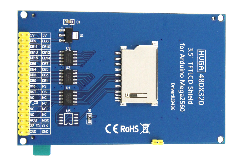
Hello, i've got LCD TFT ILI9486 which uses 8-bit parallel interface. So in that i case i have lcdts_io_gpio8.c/h files respectively.
  /*
   * 5 controll pins (CS, RS, WR, RD, RST) + 8 data pins + backlight pin

   * note: since the LCD and touch are on the same pins,
   * the simultaneous use of these should be excluded.
   * In multi-threaded interruption mode, collision prevention must be avoided!
   */

  //=============================================================================
  /* Lcd controll pins assign (A..K, 0..15) */
  #define LCD_CS            B, 0
  #define LCD_RS            A, 4
  #define LCD_WR            A, 1
  #define LCD_RD            A, 0  /* If not used leave it that way */
  #define LCD_RST           C, 1  /* If not used leave it that way */

  /* Lcd data pins assign (A..K, 0..15) */
  #define LCD_D0            A, 9
  #define LCD_D1            C, 7
  #define LCD_D2            A, 10
  #define LCD_D3            B, 3
  #define LCD_D4            B, 5
  #define LCD_D5            B, 4
  #define LCD_D6            B, 10
  #define LCD_D7            A, 8

  /* Backlight control
     - BL: A..K, 0..15 (if not used -> X, 0)
     - BL_ON: 0 = active low level, 1 = active high level */
  #define LCD_BL            X, 0  /* If not used leave it that way */
  #define LCD_BLON          0

  /*-----------------------------------------------------------------------------
  Touch I/O pins and A/D channels
  In the lcd board are paralell pins
   - TS_XM <- LCD_RS
   - TS_XP <- LCD_D6
   - TS_YM <- LCD_D7
   - TS_YP <- LCD_WR */

  /* ADC converter number (1, 2, 3, or 0 if not used)
     - 0: analog touchscreen driver not used
     - 1..3: A/D converter number */
  #define TS_ADC            1

  /* If you use different pins for touch AD conversion than for lcd control, specify it
     (When using the same pins or not using a touchscreen -> X, 0
      in this case, LCD_RS and LCD_WR will be the selected AD pin on the touchscreen) */
  #define TS_XM_AN          A, 4  /* If not used leave it that way */
  #define TS_YP_AN          A, 1  /* If not used leave it that way */

  /* Select the AD channels */
  #define TS_XM_ADCCH       1
  #define TS_YP_ADCCH       0

  /* Wait time for LCD write and read pulse and touchscreen AD converter
     - First, give 10, 20, 500 values, then lower them to speed up the program.
       (values also depend on processor speed and LCD display speed) */
  #define LCD_WRITE_DELAY  0
  #define LCD_READ_DELAY   1
  #define TS_AD_DELAY     500
To watch SWO i use STM32CubeProgrammer with SWV. I cannot understand why output is like this:
and why after 3 checked rectangles it does not show me TS_CINDEX values.
I've checked that longer SWO buffers works corrcectly.